00197790-01.pdf - 第18页
Installation Guide Ausgabe 08/2014 Edition 18 2.5 Auxiliary switch block plug the auxiliar y switches next to K6 and K9 Connect the black wire 03102820-01 to the auxiliar y switch at K6 and the wire 2 to the auxiliar…
Installation Guide Ausgabe 08/2014 Edition
17
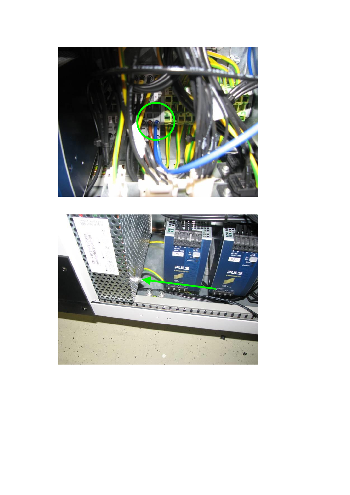
connect the blue wire 03102822-01 to Neutral at the clamping block X99 shown in the picture
route the wire 03102818-01 to the outside of the switching unit
Installation Guide Ausgabe 08/2014 Edition
18
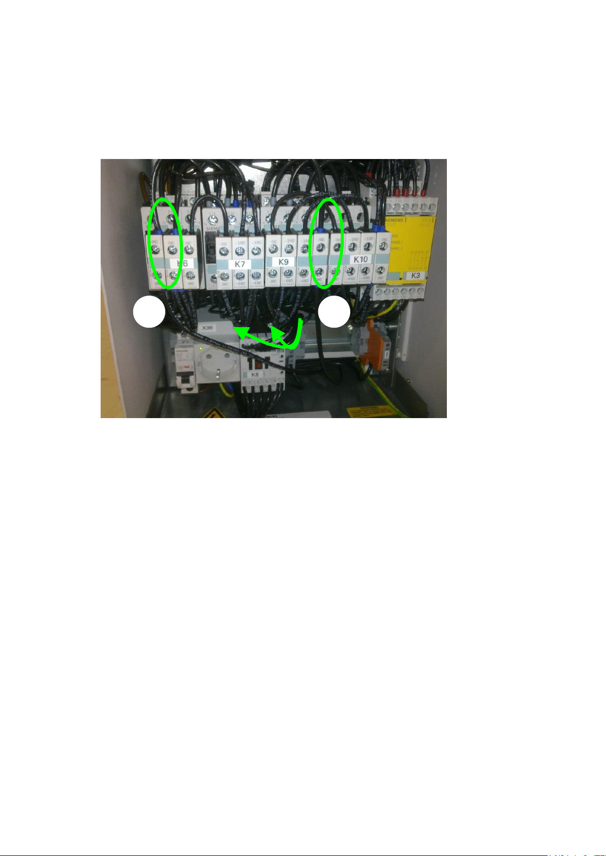
2.5 Auxiliary switch block
plug the auxiliary switches next to K6 and K9
Connect the black wire 03102820-01 to the auxiliary switch at K6 and the wire 2 to the auxiliary
switch at K9.
connect both switches K6 and K9 with cable 03102818-01 (see 1 and 2)
1
2
Installation Guide Ausgabe 08/2014 Edition
19
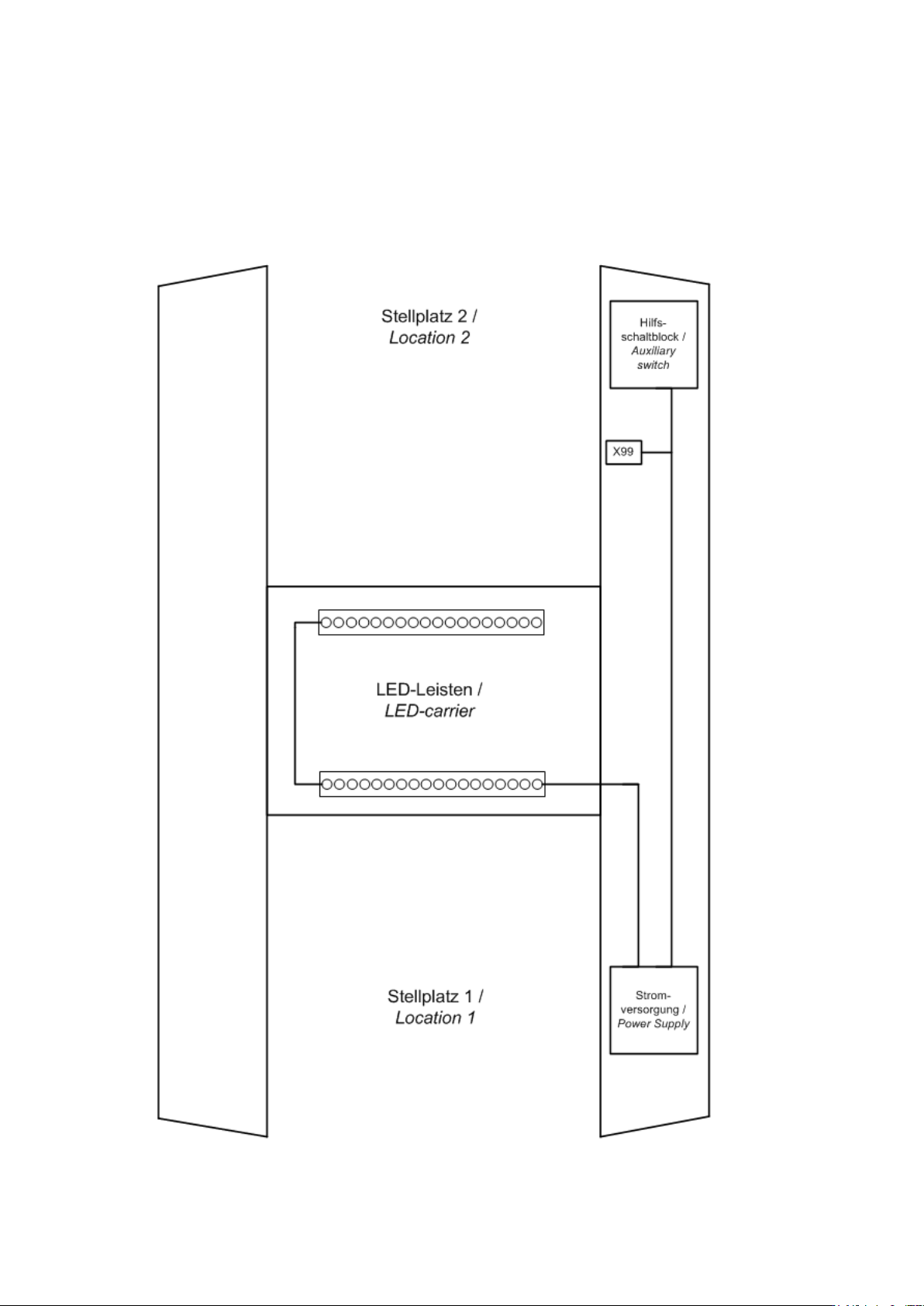
3 Appendix
3.1 Wiring diagram overview