00194086-01.pdf - 第123页
User Manual SIPLAC E CS 5 Tasks on the machine Software Vers ion SR.408.xx 03/2006 U S Edition 5.8 Dock ing the component trolley in or out 123 (8) Holes for the cen tering pi ns (9) Centerin g pins (10) Contact surfaces…
5 Tasks on the machine User Manual SIPLACE CS
5.8 Docking the component trolley in or out Software Version SR.408.xx03/2006 US Edition
122
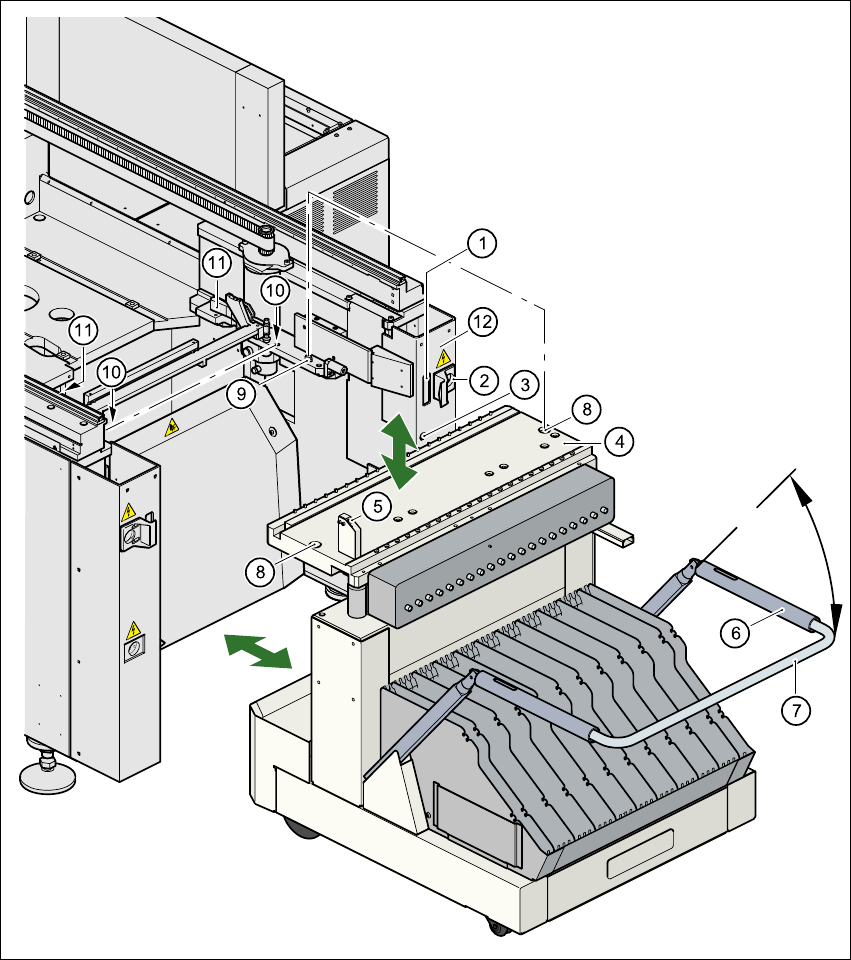
Fig. 5.8 - 2 Docking or undocking the component trolley
(1) Communication interface connector
(2) Power supply connector for the component trolley
(3) Compressed air connection
(4) Component table bed
(5) Button for raising and lowering the component table bed
(6) Actuating tube
(7) Fold-down bracket

User Manual SIPLACE CS 5 Tasks on the machine
Software Version SR.408.xx 03/2006 US Edition 5.8 Docking the component trolley in or out
123
(8) Holes for the centering pins
(9) Centering pins
(10) Contact surfaces for the slide rails of the component trolley
(11) Horizontal tensioners
(12) Movable cover that ensures that the power supply and control cables are plugged in and
removed in the correct order.
5
5.8.2 Undocking the component trolley
Æ
Click on the STOP PROCESSING PCB icon in the MAIN VIEW menu.
Æ The PCB in progress will be completed. The icons of the SINGLE FUNCTIONS menu will then
be activated.
Æ Click on the icon SINGLE FUNCTIONS GANTRY.
Æ Click on the GANTRY FUNCTIONS icon.
Æ From this menu, click on the GO TO SET-UP POSITION button.
Æ All the placement heads will move across the PCB conveyor to prevent them being damaged
when the component trolley is changed.
Æ Open protective cover of the selected gantry.
Æ Open the side screens.
Æ Open the horizontal tensioners (item 11).
Æ Pull the two actuating tubes (item 6) towards you at the same time and lift up the bracket
(item 7). Thus you will lock the raised component table bed in its top end position.
WARNING DANGER OF CRUSHING 5
When raising the component table bed, never reach into the gap between the feeders and
the used tape channel. 5
Æ Hold down the button (item 5) for raising the component table bed (item 4) until the component
table bed reaches its top end position.
Æ Unplug the component trolley power cable (item 2).
Æ Move the cover (item 12) sideways until you can unplug the control cable (item 1).
Æ Unplug the component table control cable (item 1).
Æ Disconnect the compressed air supply (item 3).
Æ Remove the component trolley.
5 Tasks on the machine User Manual SIPLACE CS
5.8 Docking the component trolley in or out Software Version SR.408.xx03/2006 US Edition
124
5.8.3 Docking the component trolley
PLEASE NOTE 5
Shorten the component tapes on the front end of the S feeder to approximately 3 cm before you
dock in the component trolley.
CAUTION 5
Æ Check that the placement head is outside the range of the component trolley.
Æ When docking the component trolley, ensure that the table bed is in its top end position and
the bracket (item 7) is folded up.
Æ Make sure that the contact surface (item 10) for the component table bed is clean.
Æ CAREFULLY push the component trolley into the placement system.
Æ Connect the compressed air supply (item 3).
Æ Plug in the control cable (item 1).
Æ Move the cover (item 12) over the control cable plug to expose the power supply socket.
Æ Plug in the power cable (item 2) for the component trolley.
Æ Pull the two actuating tubes (item 6) towards you at the same time and then lower the trolley
bracket (item 7) in order to be able to lower the component table bed.
Æ Check that the centering holes in the component table bed lie precisely over the centering pins
of the placement system.
Æ Hold down the button (item 5) until the component table bed reaches its top end position.
WARNING DANGER OF CRUSHING 5
When lowering the component table bed, never reach into the gap between the feeders and
the used tape channel. 5
Æ Release the button. The component table bed will descend.
Æ Ensure that the centering pins engage in the centering holes in the component table bed and
that the component table bed is fully lowered.
Æ Lock the two horizontal tensioners (item 11).
Æ Close the side screens and protective cover.
Æ Press the start button to start the placement system.