00194086-01.pdf - 第63页
User Manual SIPLAC E CS 3 Technical data Software Vers ion SR.408.xx 03/2006 U S Edition 3.1 Descript ion of the machine 63 3.1.1 T e chnica l dat a - mac hine ov erview 3 *) The CS c an be equipped to place 0201 compone…
3 Technical data User Manual SIPLACE CS
3.1 Description of the machine Software Version SR.408.xx03/2006 US Edition
62
The placement heads pick up components from stationary feeders and use them to populate the
PCB clamped on the PCB conveyor. 6-segment Collect&Place heads equipped with a compo-
nent camera can process size 0201 to 18.7 mm x 18.7 mm components.
The concept behind the automatic placement system
– with its stationary feeders,
– PCBs that do not move during placement
– and positionable placement heads
has a number of significant benefits:
– For example, the flexible 6-segment Collect&Place heads combined with automatic nozzle
changers enable the nozzle configuration to be changed temporarily and automatically
adapted to receive different component sizes. You can also optimize the traversing paths and
the placement sequence.
– With stationary feeders, even the tiniest components are picked up reliably.
– The components cannot slip on the PCB during placement (as is often the case with moving
PCBs) since the PCB does not move.
– Sophisticated optical centering systems (vision modules) for components and PCBs also en-
sure high component positioning accuracy.
– Components can be topped up and tapes can be spliced without stopping the machine.
– Prepared component trolleys enable the placement system to be retooled without long stop-
pages.

User Manual SIPLACE CS 3 Technical data
Software Version SR.408.xx 03/2006 US Edition 3.1 Description of the machine
63
3.1.1 Technical data - machine overview
3
*) The CS can be equipped to place 0201 components. Please consult the factory if you require this.
Placement procedure Collect&Place
Component range
*)
6-segment-Collect&Place head with
standard component vision camera
Max. component height
From 0,6 mm x 0,3 mm to 18,7 mm x 18,7 mm
(0201 to PLCC44, SO32, DRAM)
6 mm (10,7 mm available upon request)
Maximum placement rate (Benchmark)
with two 6-segment Collect&Place heads 20,000 comp/h
6-segment Collect&Place head
Angular accuracy
Placement accuracy
± 0.5° / 3 σ ± 0.7°/ 4 σ
± 68µm / 3 σ ± 90 µm / 4 σ
PCB format
(length x width) 50 mm x 50 mm to 508 mm x 460 mm
(2" x 2" to 20" x 18")
Long board: length up to 610 mm (24") (avail-
able upon request)
PCB thickness 0.5 mm to 4.5 mm
PCB changeover time 2.5 sec
Feeder capacity 118 tracks à 8 mm
Component supply
Feeder module types
Component trolley
Component tapes, stick magazines, bulk
cases, surf tapes (see section 6
)
Operating system Microsoft Windows XP / RMOS
Connection Inline or stand alone
Space required 4 m² / module
3 Technical data User Manual SIPLACE CS
3.2 Electrical and pneumatic connection points Software Version SR.408.xx03/2006 US Edition
64
3.2 Electrical and pneumatic connection points
3
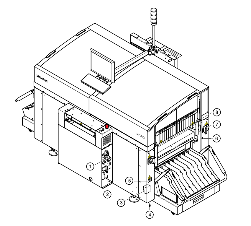
Fig. 3.2 - 1 Electrical and pneumatic connection points on the placement system part 1
3
(1) Compressed air unit
(2) Connection for compressed air line
(3) Main power filter Z1
(4) Hole for power cable
(5) Service socket
(6) Compressed air connection for component trolleys
(7) Power supply connection for component trolley
(8) Communications connection for component trolley