00194086-01.pdf - 第75页
User Manual SIPLAC E CS 3 Technical data Software Vers ion SR.408.xx 03/2006 U S Edition 3.5 Controls 75 3.5.3.1 Controls on the input and outpu t sides of the placement machine EMERGENCY-STOP button, start and stop butt…

3 Technical data User Manual SIPLACE CS
3.5 Controls Software Version SR.408.xx03/2006 US Edition
74
provides the screen display. The ultra-flat IBM-compatible PC keyboard incorporates a trackball
for controlling the mouse.
Indicator lamp
The sequence of colors is white - green - white. It signals operating statuses and malfunctions of
the placement machine (see chapter 5
).
Component barcode reader
The Datalogic DL910 component barcode reader is attached to a bracket on the output side of
the machine. It enables the components to be set up and topped up quickly and reliably.
3.5.3 Ergonomic arrangement of the controls
Figure 3.5 - 1 on page 71 provides an overview of the position of the controls. They are subdi-
vided into the following groups:
Operating panel on the PCB input side with
– Start button
– Stop button
– EMERGENCY STOP push-button
– Main power switch
Operating panel on the PCB output side with
– EMERGENCY STOP push-button
– Start button
– Stop button
– Component counter
– Key-operated switch
– Component barcode reader
Pivoting bracket with
– Monitor and
– Keyboard
User Manual SIPLACE CS 3 Technical data
Software Version SR.408.xx 03/2006 US Edition 3.5 Controls
75
3.5.3.1 Controls on the input and output sides of the placement machine
EMERGENCY-STOP button, start and stop buttons
There is an EMERGENCY-STOP button, a start button and a stop button on both the input and
output sides of the PCB conveyor. This arrangement was adopted for the EMERGENCY STOP
buttons because it enables them to be reached quickly and easily from any position.
In addition, it is important to have an unrestricted view of the placement heads and placement
area during preventive maintenance, servicing and setting up work in order to be able to check
all the operations carried out inside the machine. This particularly important during testing
phases or when starting single functions, for example.
Key switch
The key switch is located on the operating panel on the PCB output belt. It is only needed for set-
ting up and servicing work so, for reasons of efficiency, it is positioned near the start and stop
buttons.
Main power switch
The main switch is part of the power supply unit, so it is positioned on the left-hand side of the
PCB input belt. It is located here because it is only needed for switching the placement system
on or off and is therefore not subject to frequent use.
3.5.3.2 Controls on the placement system console
Monitor and keyboard
The station computer, monitor and keyboard are all mounted on the console. They are arranged
so that any person who is at least 1.60 m tall can work comfortably and efficiently.
Component barcode reader
The two component trolleys for supplying components are arranged on the right and left of the
placement system. For this reason, the component barcode reader was arranged on the PCB
output side so that all the barcode labels are equally accessible. This enables the operators to
work comfortably and efficiently during the component set-up and filling checks.
3 Technical data User Manual SIPLACE CS
3.6 Component barcode reader Software Version SR.408.xx03/2006 US Edition
76
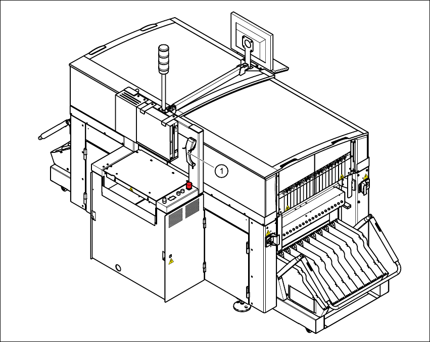
3.6 Component barcode reader
3.6.1 General
With the placement system, a barcode reader can be used to check that the track allocation is
correct and to read component data from component reels.
Fig. 3.6 - 1 Component barcode reader
(1) Component barcode reader