manual-phne-nano-preheater-0026172_ID-202812_EN.pdf - 第12页
Maintenance - Befo re ca rr y ing o ut ma inte nan ce or s torag e, always all ow the e qui pme nt to coo l dow n. - Che ck p er iod ica lly t hat the e qu ipm ent is c le an. - Use a d amp c loth w hen c le ani ng. Al c…
PHXLE
PHXL-SA
PHB-SA
PHS-SA
PHN-SA
PHBE DESPIECE PHB
PHSE
PHNE
OK
14:15
20
º
C
Power
45%
TC1
45
º
C
Selected 120
º
C
TC2
P
100
º
C
20
º
C
TC3
P
100
º
C
20
º
C
TC4
P
100
º
C
14:15
20
º
C
Power
45%
Selected power
45
%
TC1
P
100
º
C
20
º
C
TC3
P
100
º
C
20
º
C
TC4
P
100
º
C
20
º
C
TC2
P
100
º
C
14:15
20
º
C
T1
23
º
C
20
5’ 8’
º
C
120
º
C
T3
24
º
C
T7
StopPROFILE1
200
100
14:15
31
º
C
27
º
C
TC1
TC2
StopPROFILE1
200
100
14:15
200
150
100
50
300
250
14:15
5m 00s
120
º
C
PROFILE1
200
100
14:15
30
º
C
Power
45%
Selected power
45
%
TC1
C
100
º
C
---
º
C
TC2
P
100
º
C
0 60 120 180 240 300
Point
2/3
Temp Time
2m 00s
14:15
20
º
C
20
º
C
TC1
TC2
20
º
C
TC3
20
º
C
TC4
StopPROFILE1
200
100
Ext. Temp [ºC]Power [%]
14:15
20
º
C
Power
45%
TC1
45
º
C
Selected 120
º
C
TC2
P
100
º
C
20
º
C
TC3
P
100
º
C
20
º
C
TC4
P
100
º
C
14:15
20
º
C
Power
45%
TC1
45
º
C
Selected 120
º
C
Max. Rate
1.6ºC/s
Max. Rate
1.6ºC/s
TC2
C
100
º
C
20
º
C
TC3
P
100
º
C
20
º
C
TC4
P
100
º
C
14:15
20
º
C
Power
45%
Selected power
45
%
14:15
TC5
P
100
º
C
20
º
C
TC7
P
100
º
C
20
º
C
TC8
P
100
º
C
20
º
C
TC6
P
100
º
C
20
º
C
TC5
P
100
º
C
14:15
20
º
C
Power
45%
TC1
25
º
C
Selected 120
º
C
TC2
P
100
º
C
14:15
20
º
C
Power
45%
TC1
25
º
C
Selected 120
º
C
TC2
P
100
º
C
14:15
20
º
C
Power
45%
TC1
45
º
C
Selected 120
º
C
TC2
C
100
º
C
20
º
C
TC3
P
100
º
C
20
º
C
TC4
P
100
º
C
20
º
C
TC5
P
100
º
C
20
5’ 8’
º
C
120
º
C
80
º
C
100
º
C
5’ 8’5’30”3’30” 8’
20
º
C
120
º
C
80
º
C
TC1
TC2
TC3
TC4
ROBOT
AUX.
PEDAL
Hot
Zone B
Zone A
Zone A
Zone B
Hot
Hot
Zone B
Zone A
Zone A
Zone B
Hot
TC1
TC2
TC3
TC4
ROBOT
AUX.
PEDAL
detalle parte trasera
TC1
TC2
TC3
TC4
ROBOT
AUX.
PEDAL
TC1
TC2
TC3
TC4
ROBOT
AUX.
PEDAL
Hot
Zone B
Zone A
Zone A
Zone B
Hot
Hot
Zone B
Hot
Zone B
Zone A
Zone A
Max. Rate
1.6ºC/s
Max. Rate
1.6ºC/s
Max. Rate
1.6ºC/s
Max. Rate
1.6ºC/s
Work mode
Mode
Time to stop
Thermocouples
Max Rate
Back
None
2min
Temp.
14:15
Work mode
Mode
Time to stop
Thermocouples
Max Rate
Back
None
2min
Temp.
1.6ºC/s
Max Rate
Min 0.1ºC/s Max 2.0ºC/s
PHXLE
PHXL-SA
PHB-SA
PHS-SA
PHN-SA
PHBE DESPIECE PHB
PHSE
PHNE
OK
14:15
20
º
C
Power
45%
TC1
45
º
C
Selected 120
º
C
TC2
P
100
º
C
20
º
C
TC3
P
100
º
C
20
º
C
TC4
P
100
º
C
14:15
20
º
C
Power
45%
Selected power
45
%
TC1
P
100
º
C
20
º
C
TC3
P
100
º
C
20
º
C
TC4
P
100
º
C
20
º
C
TC2
P
100
º
C
14:15
20
º
C
T1
23
º
C
20
5’ 8’
º
C
120
º
C
T3
24
º
C
T7
StopPROFILE1
200
100
14:15
31
º
C
27
º
C
TC1
TC2
StopPROFILE1
200
100
14:15
200
150
100
50
300
250
14:15
5m 00s
120
º
C
PROFILE1
200
100
14:15
30
º
C
Power
45%
Selected power
45
%
TC1
C
100
º
C
---
º
C
TC2
P
100
º
C
0 60 120 180 240 300
Point
2/3
Temp Time
2m 00s
14:15
20
º
C
20
º
C
TC1
TC2
20
º
C
TC3
20
º
C
TC4
StopPROFILE1
200
100
Ext. Temp [ºC]Power [%]
14:15
20
º
C
Power
45%
TC1
45
º
C
Selected 120
º
C
TC2
P
100
º
C
20
º
C
TC3
P
100
º
C
20
º
C
TC4
P
100
º
C
14:15
20
º
C
Power
45%
TC1
45
º
C
Selected 120
º
C
Max. Rate
1.6ºC/s
Max. Rate
1.6ºC/s
TC2
C
100
º
C
20
º
C
TC3
P
100
º
C
20
º
C
TC4
P
100
º
C
14:15
20
º
C
Power
45%
Selected power
45
%
14:15
TC5
P
100
º
C
20
º
C
TC7
P
100
º
C
20
º
C
TC8
P
100
º
C
20
º
C
TC6
P
100
º
C
20
º
C
TC5
P
100
º
C
14:15
20
º
C
Power
45%
TC1
25
º
C
Selected 120
º
C
TC2
P
100
º
C
14:15
20
º
C
Power
45%
TC1
25
º
C
Selected 120
º
C
TC2
P
100
º
C
14:15
20
º
C
Power
45%
TC1
45
º
C
Selected 120
º
C
TC2
C
100
º
C
20
º
C
TC3
P
100
º
C
20
º
C
TC4
P
100
º
C
20
º
C
TC5
P
100
º
C
20
5’ 8’
º
C
120
º
C
80
º
C
100
º
C
5’ 8’5’30”3’30” 8’
20
º
C
120
º
C
80
º
C
TC1
TC2
TC3
TC4
ROBOT
AUX.
PEDAL
Hot
Zone B
Zone A
Zone A
Zone B
Hot
Hot
Zone B
Zone A
Zone A
Zone B
Hot
TC1
TC2
TC3
TC4
ROBOT
AUX.
PEDAL
detalle parte trasera
TC1
TC2
TC3
TC4
ROBOT
AUX.
PEDAL
TC1
TC2
TC3
TC4
ROBOT
AUX.
PEDAL
Hot
Zone B
Zone A
Zone A
Zone B
Hot
Hot
Zone B
Hot
Zone B
Zone A
Zone A
Max. Rate
1.6ºC/s
Max. Rate
1.6ºC/s
Max. Rate
1.6ºC/s
Max. Rate
1.6ºC/s
Work mode
Mode
Time to stop
Thermocouples
Max Rate
Back
None
2min
Temp.
14:15
Work mode
Mode
Time to stop
Thermocouples
Max Rate
Back
None
2min
Temp.
1.6ºC/s
Max Rate
Min 0.1ºC/s Max 2.0ºC/s
JBC
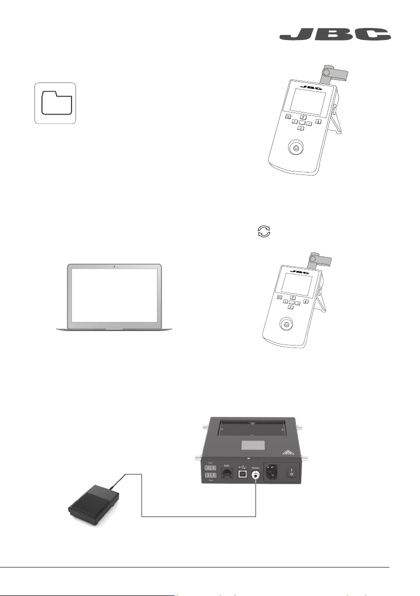
Update File
Files
Export Graphics
Insert a USB flash drive into
the USB-A connector to save
your soldering process in
CSV format.
Export / Import Profiles
Insert a USB flash drive into
the USB-A connector to
export/import profiles.
Update the Station Software
1. Download the JBC Update File from
www.jbctools.com/software.html and save
it on a USB flash drive. (Preferably one with no
other files).
2. Insert the USB flash drive into the console.
The icon is displayed while updating.
Files
Working with Pedal
Press the pedal to start heating and press again to stop as if it were the button on the console.
Once the Work Mode is set, the Heater Unit can work without the console using the pedal.
www.jbctools.com
11
P405
Pedal
(not included)
PHNE
Preheater
Unit
Maintenance
- Before carrying out maintenance or storage, always
allow the equipment to cool down.
- Check periodically that the equipment is clean.
- Use a damp cloth when cleaning. Alcohol can only
be used to clean the metal parts.
- Only if it is absolutely necessary and if cleaning
with isopropyl alcohol (IPA) is not enough, it is
recommended to use a scraper to remove dirt in
the glass area.
- Replace any defective or damaged parts. Use original
JBC spare parts only.
- Repairs should only be performed by a JBC authorized
technical service.
1
1
12
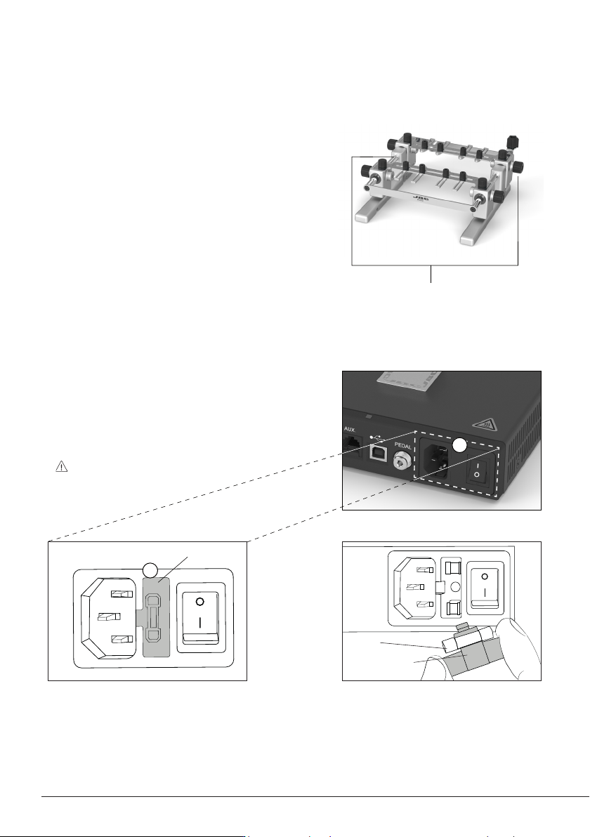
Clean periodically
the Sliding Guide
Axes
Fuse Holder
Fuse Holder
Fuse
Pull out the fuse holder, if necessary use
a tool to lever it off.
Take the blown fuse out and press the
new one into the fuse holder. Finally clip
the fuse holder back into place.
- A blown fuse can be replaced by the user itself.
The fuse is located between the power supply
connector and the on/off switch (1). To replace a
blown fuse, proceed as described below.
Important: make sure that the preheater
is disconnected from the
power supply.
Safety
It is imperative to follow safety guidelines to prevent electric
shock, injury, fire or explosion.
- Do not use the units for any purpose other than PCB preheating. Incorrect use may cause a fire.
- The mains cable must be plugged into approved bases. Make sure that it is properly grounded
before use. When unplugging it, hold the plug, not the wire.
- The temperature of accessible surfaces may remain high after the unit is turned off. Handle with care.
- Do not leave the appliance unattended when it is on.
- Do not cover the ventilation grills. Heat can cause inflammable products to ignite.
- Heat can cause inflammable products to ignite even when out of sight.
- Be careful with the remains of liquid tin. In contact with the skin, it can cause burns.
- Avoid flux coming into contact with skin or eyes to prevent irritation.
- Be careful with the smoke produced when soldering.
- Keep your workplace clean and tidy. Wear appropriate protection glasses and gloves when working
to avoid personal harm.
- This appliance can be used by children over the age of eight as well as persons with reduced physical,
sensory or mental capabilities or lacking experience provided that they have been given adequate
supervision or instruction concerning the use of the appliance and understand the hazards involved.
Children must not play with the appliance.
- Maintenance must not be carried out by children unless supervised.
www.jbctools.com
13