Manual_HON_219_20_GB.pdf - 第5页
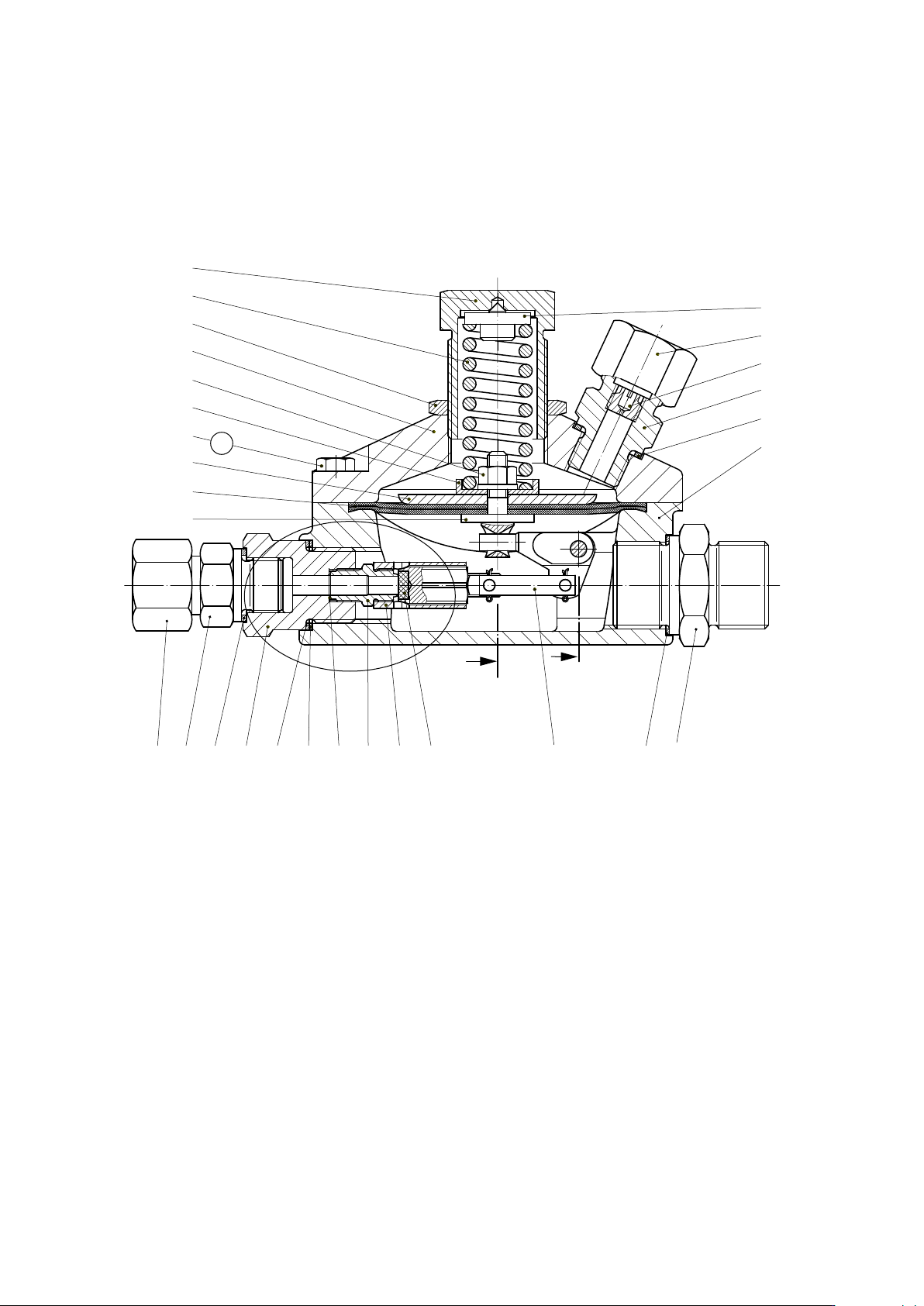
A 1 2 3 4 5 6 8 9 W 10 11 12 13, 14 15 16 17 W 18 19, 21 22 23 24 25 26 27 28 29 30 32 33 20 W W W W W B X M A 4.1.1 Spar e par ts drawing – type with measuring unit M Jet - Ø2, Ø3.7 and Ø5.5 M A Be sure to comply with t…
•
•
•
!
•
219.20 p.04
2. Specic operating instructions
2.1 Changing setpoints
Increase the setpoint by turning the setpoint adjusting screw. Having changed the setpoint of the
control stage, be sure to secure the setpoint adjuster using at head screw (213, 313) or nut (3).
Be sure to adjust the connection between lever and lever eye to the central position.
Find the central position by test-turning the diaphragm all the way to the stops on the left and on the right.
3.1 Tightening torques M
A
in Nm
Screws & bolts – item no. Tightening torques M
A
in Nm
8, 208, 308 8
3.2 Lubricants
Components Lubricants HON part no.
All O rings
Clamping area of the diaphragm Silicone grease 27081
Slip faces of pistons Slip agent (ammonia) 28211
Thread of setpoint adjusting screw/
adjusting spindle
All fastening screws and Assembly paste 27091
screwed pipe connections Slip agent (ammonia) 28211
3. Specic maintenance instructions
Note
Safety relief valve does not allow the setpoint to be changed.
The following setpoints have been pre-set:
– 5 bar approx. – for measuring units M, G, GS, F
– 10 bar approx. – for measuring unit V
Danger
Replacing distance piece (23)
Do not dismount inlet connection piece (23, 59).
When installing the pressure reducer on a pipework system and when removing it, be sure
to use an SW wrench to secure inlet connection piece (23, 59) and outlet connection piece
(33) so they don't move and/or come loose.
When replacing jet connecting piece (23) and/or distance piece with jet and piston guide
(28), be sure to observe proper piston mounting position.
See also “Mounting and dismounting sealing shim (29)”.
Mounting and dismounting sealing shim (29)
When dismounting piston and seal (29): Do not start to unscrew jet connecting piece (59)
and/or distance piece with jet and piston guide (23, 27, 28) before you have dismounted
cap (4) from body (18).
When mounting piston and seal (29): always mount together with jet connecting piece
(59) and/or distance piece with jet and piston guide (23, 27, 28) while diaphragm (10) and
cap (4) are still o. Be sure to nd the correct mounting position of the piston inside the
jet.
A
1
2
3
4
5
6
8
9
W 10
11
12
13, 14
15
16
17 W
18
19, 21 22 23 24 25 26 27 28 29 30 32 33
20 W W W W W
B
X
M
A
4.1.1 Spare parts drawing – type with measuring unit M
Jet - Ø2, Ø3.7 and Ø5.5
M
A
Be sure to comply with tightening torques in table on page 4.
W Parts should be held in stock for maintenance purposes.
For section views see page 6.
219.20 p.05
52
53 W
54
55
56
57, 58
50 51
W
60 61 62
W
59 24 (25) 29 30
W W
59 24 (25) 31 29 30
W W
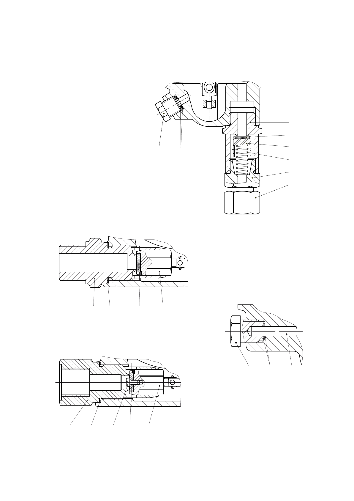
Detail “X”
Type with jet - Ø 8
W Parts should be held in stock for maintenance purposes.
Partial section A
Safety valve
219.20 p.06
4.1.1.1 Sections
Partial section B
Detail “X”
Type with jet - Ø10