SIPLACE D1 规格说明书英文版.pdf - 第13页
13 Placement Heads Pick & Place head Pick & Place head fine-pitch camera CO camera type 36 Pick & Place head fine-pitch camera CO camera type 33 Pick & Place head flip-chip camera CO camera type 25 Compon…
12
Placement Heads
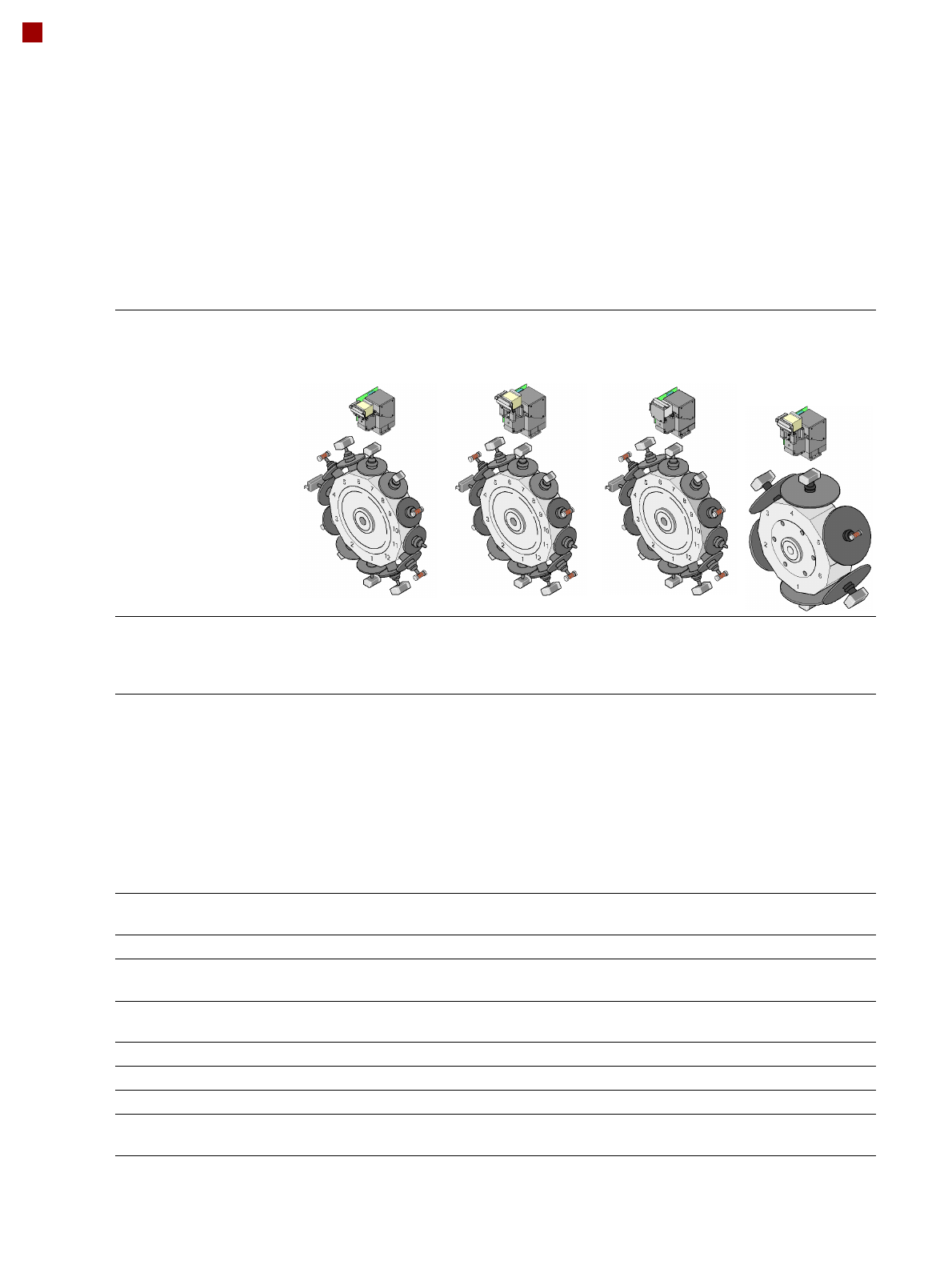
Collect&Place Heads
12-nozzle
Collect&Place head
CO camera type 28
12-nozzle
Collect&Place head
CO camera type 29
12-nozzle
Collect&Place head
CO camera type 38
6-nozzle
Collect&Place
head
CO camera type 29
Component range
a
a) Please note that the range of components that can be placed is also affected by the pad geometry, customer-specific
standards, component packaging tolerances and component tolerances
0402 to PLCC44,
BGA, µBGA, flip-
chip, TSOP, QFP, SO
to SO32, DRAM
0201
b
to flip-chip, bare
die, PLCC44, BGA,
µBGA, TSOP, QFP,
SO to SO32, DRAM
b) With 0201 package
01005
c
to 16 x
16 mm²
c) With 01005 package
0201to 27 x
27 mm²
Component specification
max. height
min. lead pitch
min. lead width
min. ball pitch
min. ball diameter
min. dimensions
max. dimensions
max. weight
6 mm
0.5 mm
0.2 mm
0.35 mm
0.2 mm
1.0 x 0.5 mm²
18.7 x 18.7 mm²
2 g
6 mm
0.3 mm
0.15 mm
0.25 mm
0.14 mm
0.6 x 0.3 mm²
b
18.7 x 18.7 mm²
2 g
6 mm
0.25 mm
0.1 mm
0.25 mm
0.14 mm
0.4 x 0.2 mm²
16 x 16 mm²
2 g
8.5 mm
0.3 mm
0.15 mm
0.25 mm
d
0.35 mm
e
0.14 mm
d
0.2 mm
e
0.6 x 0.3 mm²
27 x 27 mm²
5 g
d) For components < 18 x 18 mm²
e) For components 18 x 18 mm²
Programmable set-down
force
2.4 N - 5.0 N 2.4 N - 5.0 N 2.4 N - 5.0 N 2.4 N - 5.0 N
Nozzle types 9xx 9xx 9xx 8xx, 9xx
X/Y accuracy
f
f) The accuracy value was measured using the vendor-neutral IPC standard
± 50 µm/3
± 67 µm/4
± 50 µm/3
± 67 µm/4
± 50 µm/3
± 67 µm/4
± 52.5 µm/3
± 70 µm/4
Angular accuracy ± 0.53°/3
± 0.71°/4
± 0.53°/3
± 0.71°/4
± 0.53°/3
± 0.71°/4
± 0.225°/3
± 0.3°/4
Component range 98% 98.5% 96% 99.8%
Component camera type 28 29 38 29
Illumination levels 5 5 5 5
Possible illumination level
settings
256
5
256
5
256
5
256
5
13
Placement Heads
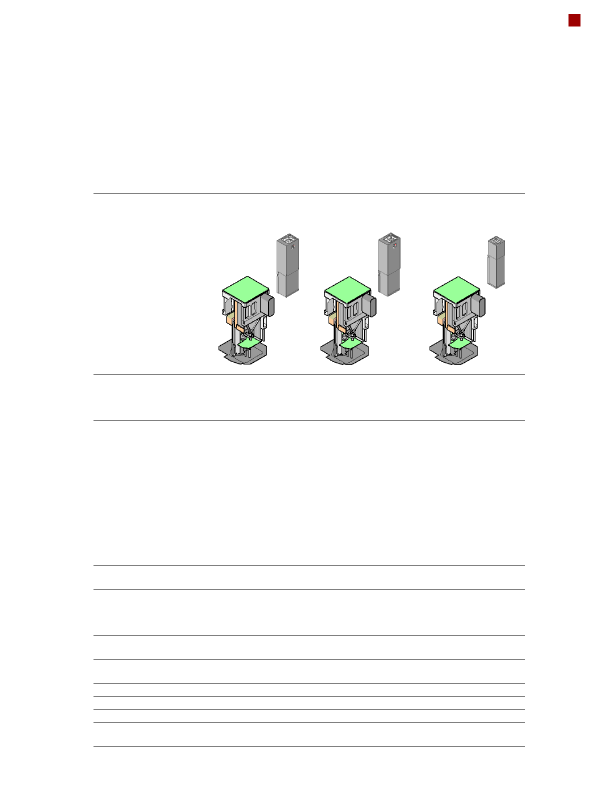
Pick&Place head
Pick&Place head
fine-pitch camera
CO camera type 36
Pick&Place head
fine-pitch camera
CO camera type 33
Pick&Place head
flip-chip camera
CO camera type 25
Component range
a
a) Please note that the range of components that can be placed is also affected by the pad geometry, customer-
specific standards, component packaging tolerances and component tolerances
0603 to SO, PLCC,
QFP, BGA, special
components, bare
dies, flip-chips
0402 to SO, PLCC,
QFP, BGA, special
components, bare
dies, flip-chips
0201 to SO, PLCC, QFP,
sockets, plugs, BGA, spe-
cial components, bare
dies, flip-chips, shields
Component specs
max. height
min. lead pitch
min. lead width
min. ball pitch
min. ball diameter
min. dimensions
max. dimensions
max. weight
b
b) If standard nozzles are used
19 mm
0.4 mm
0.24 mm
0.56 mm
0.32 mm
1.6 x 0.8 mm²
32 x 32 mm²
(single measurement)
85 x 85 mm² or
max. 200 x 125 mm²
(with restrictions)
100 g
19 mm
0.3 mm
0.15 mm
0.35 mm
0.2 mm
1.0 x 0.5 mm²
55 x 45 mm²
(single measurement)
85 x 85 mm² or
max. 200 x 125 mm²
(with restrictions)
100 g
19 mm
0.25 mm
0.1 mm
0.14 mm
0.08 mm
0.6 x 0.3 mm²
16 x 16 mm²
(single measurement)
100 g
Programmable set-down
force 1.0 N - 15 N 1.0 N - 15 N 1.0 N - 15 N
Nozzle types
c
c) Over 300 different nozzles and 100 gripper types are available, with an extensive nozzle database available
online
5xx (standard)
4xx + adapter
8xx + adapter
9xx + adapter
5xx (standard)
4xx + adapter
8xx + adapter
9xx + adapter
5xx (standard)
4xx + adapter
8xx + adapter
9xx + adapter
X/Y accuracy
d
d) The accuracy value was measured using the vendor-neutral IPC standard
± 37.5 µm/3
± 50 µm/4
± 37.5 µm/3
± 50 µm/4
± 30 µm/3
± 40 µm/4
Angular accuracy ± 0.053°/3
± 0.071°/4
± 0.053°/3
± 0.071°/4
± 0.053°/3
± 0.071°/4
Component range 99.8% 99.9% 99.8%
Component camera type 36 33 25
Illumination levels 6 6 6
Possible illumination
level settings
256
6
256
6
256
6
14
Placement Heads
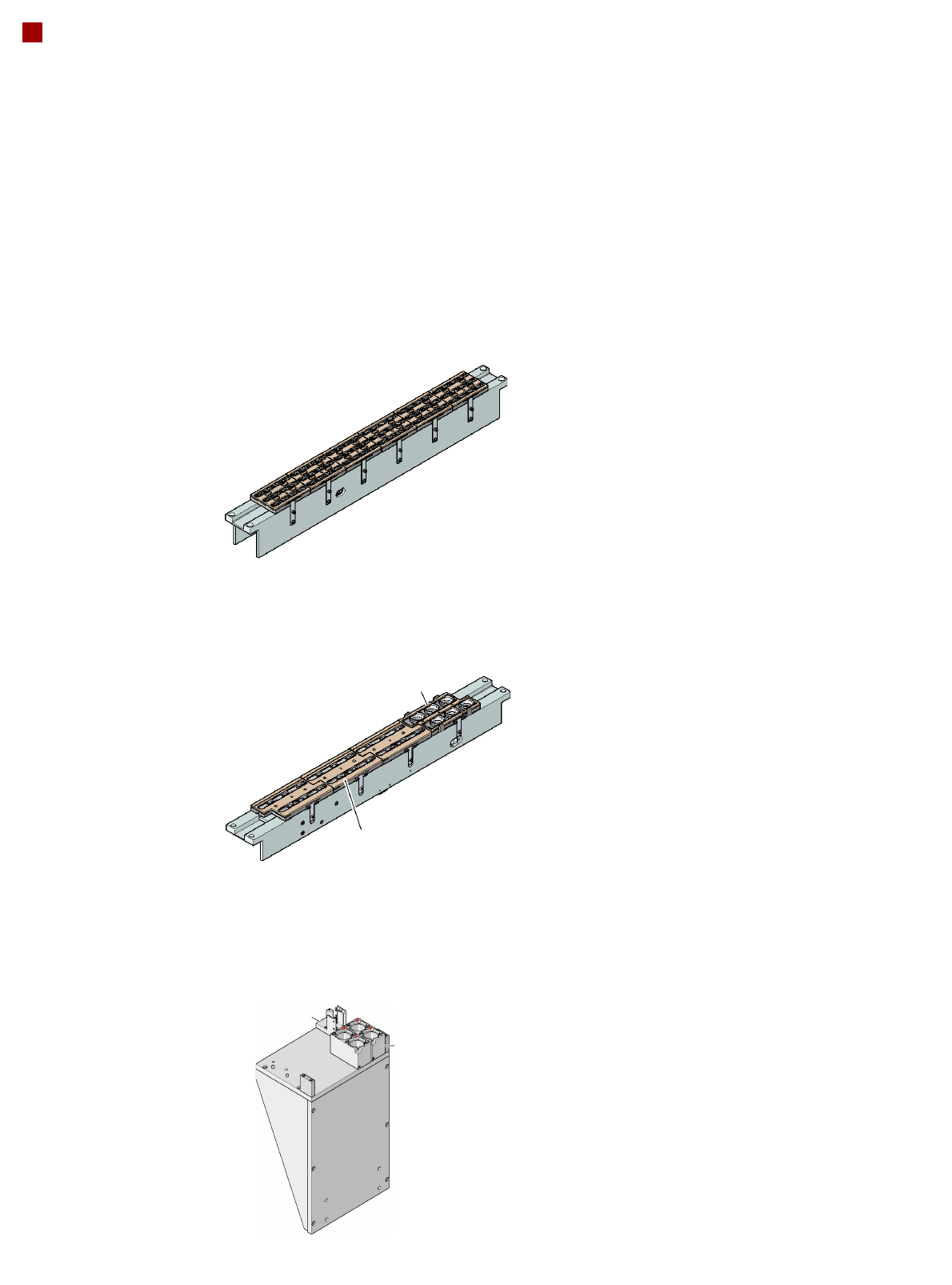
Nozzle Changers
Description
Nozzle changers increase
the flexibility of placement
heads when processing dif-
ferent components. The noz-
zle configuration can be
quickly modified for new
placement jobs. Exactly
defined positions and the per-
fect seating of the nozzle in
the garage guarantee mini-
mal radial eccentricity at the
placement head.
One nozzle changer (NCH
P&P) may be installed for the
Pick&Place head at
location 2.
The supporting plate can hold
up to 10 magazines for stan-
dard or special nozzles or
grippers.
Standard configuration:
2 x standard magazine
1 x special nozzle
Magazine for 12
type 9xx nozzles
Nozzle changer for the
12-nozzle Collect&Place head (NCH12)
Nozzle changer for the
6-nozzle Collect&Place head (NCH6)
Magazine for 6
type 9xx nozzles
Magazine for two
standard nozzles
Magazine for one
special nozzle, gripper
Nozzle changer for the TwinHead
Magazine for 6
type 8xx nozzles