Printer 710_810 v8 Air Ionizer Module.pdf - 第4页
AIR IO NIZER MODULE ADJUS TMEN TS AND SE TTINGS 25.4 Technical Reference Manual Chapter Issue 2 Oct 06 ADJUSTMENTS AND SETTINGS Air Ionizer The air ionizer has no adjustment s and the settin gs are factory set. Use the f…

AIR IONIZER MODULE
ELECTRICAL SCHEMATIC
Chapter Issue 2 Oct 06 Technical Reference Manual 25.3
ELECTRICAL SCHEMATIC
M37 Power
Supply Enclosure
Air Ionizer
M37PL11
24V SW
OV
8PL100
24V SW
OV
AIR IONIZER MODULE
ADJUSTMENTS AND SETTINGS
25.4 Technical Reference Manual Chapter Issue 2 Oct 06
ADJUSTMENTS AND SETTINGS
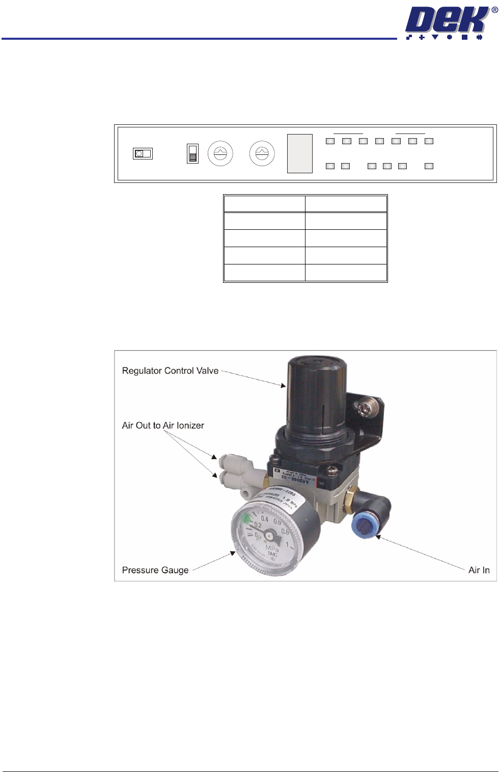
Air Ionizer The air ionizer has no adjustments and the settings are factory set. Use the
following graphic and table to ensure that the switches on the control panel of
the air ionizer are set correctly:
Air Regulator The air regulator sets the air pressure to the air ionizer and must be set between
0.15MPa and 0.20MPa (1.5 bar and 2.0 bar). To adjust the air pressure, use
the following procedure:
1. Pull the regulator control valve upwards to unlock it.
2. Turning the regulator control valve clockwise to increase the pressure or
anti-clockwise to decrease the pressure, set the pressure between 0.15MPa
and 0.20MPa (1.5 bar and 2.0 bar).
3. With the pressure set, push the regulator control valve downwards to lock it.
Switch Setting
I/O Monitor I/O
Term Off
ID 0
Freq 0
0
1
2
3
4
5
6
7
8
9
A
B
C
D
E
F
0
1
2
3
4
5
6
7
8
9
ZERO
FREQIDI/O MONITOR
OFF
TERM
ON
I.C.C. COND LEVEL
ION MONITOR
ION
ALM RC
+
-
AIR IONIZER MODULE
REPLACEMENT PROCEDURE
Chapter Issue 2 Oct 06 Technical Reference Manual 25.5
REPLACEMENT PROCEDURE
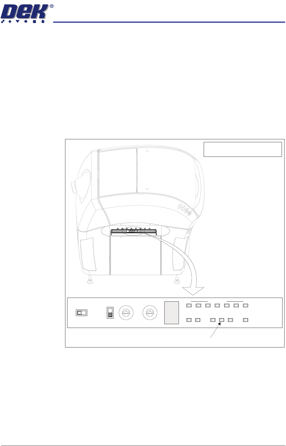
Ion Level Alarm The air ionizer monitors the quantity of ions generated and if the level deterio-
rates, the ion level alarm indicator flashes on the air ionizer control panel. The
control panel is visible through the slot in the left hand safety cover.
Figure 25-1 Air Ionizer Control Panel
If the ion level alarm indicator flashes, one or more of the eight electrodes may
be dirty or faulty. It is recommended that the electrodes are cleaned and if the
ion level alarm indicator continues to flash, replace all the electrodes. A
replacement kit of 8 electrodes is available from DEK - Pt No 167123.
Use the following procedures to clean the electrodes and replace the electrodes
if necessary.
0
1
2
3
4
5
6
7
8
9
A
B
C
D
E
F
0
1
2
3
4
5
6
7
8
9
ZERO
FREQIDI/O MONITOR
OFF
TERM
ON
I.C.C. COND LEVEL
ION MONITOR
ION
ALM RC
+
-
0
1
2
3
4
5
6
7
8
9
A
B
C
D
E
F
0
1
2
3
4
5
6
7
8
9
ZERO
FREQIDI/O MONITOR
OFF
TERM
ON
I.C.C. CONDLEVEL
IONMONITOR
ION
ALM RC
+
-
View on Left Side of Machine
NOTE
Safety cover removed for clarity.
Ion Level Alarm Indicator