TS934-TS941-user-guide.pdf - 第5页
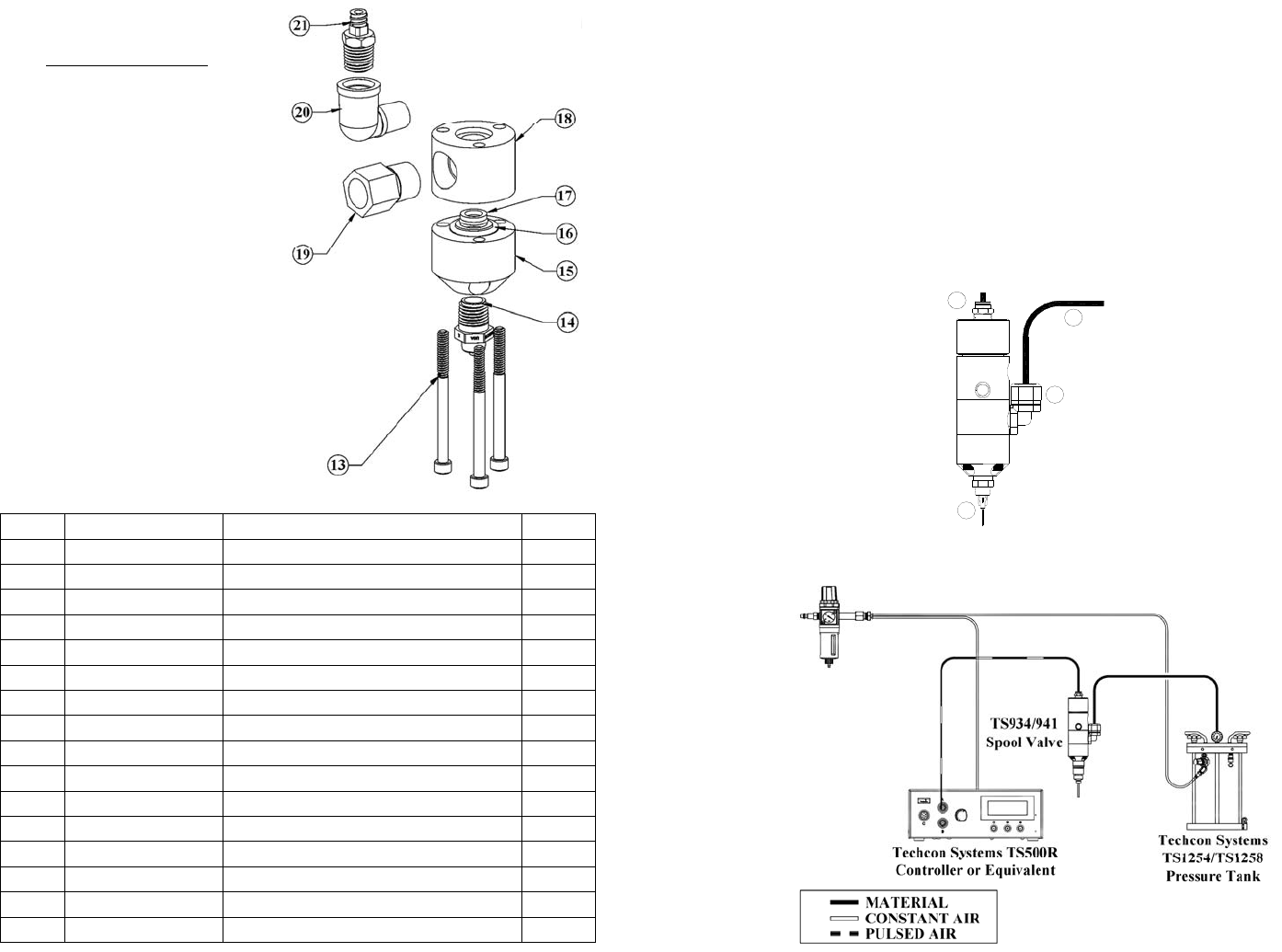
8 SPARE PARTS, CONT. Valve Front Section ITEM PART NUMBER DESCRIPTION QTY 13 TSD1103-323 Valve Assembly Screw 3/4 14 TSD931-7 Tip Adaptor ¼ '' NPT 1 15* 934-000-003 Material Outlet Block (Al) For TS934 1 15* 93…
4
2. UNPACKING AND INSPECTION
Carefully unpack the valve and examine the items contained in the carton.
These will include:
• Valve assembly
• User guide
• Fitting and Valve Air Hose
Inspect the unit for any damaged which may have occurred in transit. If such
damage has occurred, notify the carrier at once. Claim for damage must be made
by the consignee to the carrier, and should be reported to the manufacturer.
3. DESCRIPTION
The TS934/TS941 Series Spool Valve is based on a balanced spool design for a
fast “ON/OFF” dispensing action. The hardened spool slides in reinforced
UHMWPE seals and it suitable for use with fluids having a viscosity of 100 to
over 3,000,000 cps, at a pressure up to 2,500 psi (172.4bar). An internal spring
return makes the valve fully adaptable for use with Techcon Systems time/pressure
controllers.
4. THEORY OF OPERATION
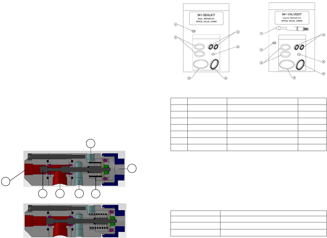
The TS934/TS941 Series Spool Valve is normally closed. When air pressure is
applied at air inlet port (1), the spool assembly (2) moves forward to the open
position, allowing the fluid to flow from the fluid inlet port (3) to the fluid outlet
port (4). Relieving the input air pressure allows the return spring (5) to pull the
spool assembly back in the close position, stopping the fluid flow. During the
closing position, the spool movement creates a “suck-back” anti-drip feature.
An Oil chamber (6) is provided, above the upper seal, to create an additional liquid
seal that will prevent moisture from being carried on the spool. The auxiliary air
inlet port (7) is provided so that the valve may be connected for air closing with or
without the spring.
Open Position
Closed Position
Figure 2.0
6
3
4
5
2
7
1
9
9. REPAIR KITS
*These kits fit all variations of Techcon Systems High Pressure Spool Valves
9.1 Alternative Seals
Techcon Systems offers alternative seal materials for different applications. The
standard seals installed in the valve are made of UHMWPE with an EPR o-ring.
Part number = TSD400-69
The following alternative seals are available:
PART NUMBER DESCRIPTION
TSD400-56
Teflon® seal with EPR expander O-ring
TSD400-58
Teflon® seal with Viton expander O-ring
TSD400-49
Teflon® seal with stainless steel expander spring
ITEM PART NUMBER DESCRIPTION QTY
1 TSD1145-1 Fiber Washer 1
2 TSD1400-115C Chamber O-Ring, EPR 2
3 TSD400-69 U-Cup Seal 2
4 TSD1400-008B Spool Shaft O-Ring, Viton 1
5 TSD1400-025A Cap O-Ring, Buna 1
6 TSD1399-2 Piston U-Cup Seal 1
7 934-000-005 Spool Shaft 1
8
SPARE PARTS, CONT.
Valve Front Section
ITEM PART NUMBER DESCRIPTION QTY
13 TSD1103-323 Valve Assembly Screw 3/4
14 TSD931-7 Tip Adaptor ¼'' NPT 1
15* 934-000-003 Material Outlet Block (Al) For TS934 1
15* 934A-000-003 Material Outlet Block (Al) For TS934A 1
15* 941-000-002 Material Outlet Block (SS) For TS941 1
15* 941A-000-002 Material Outlet Block (SS) For TS941A 1
16 TSD1400-115C Chamber O-Ring, EPR 2
17 TSD400-69 U-Cup Seal 2
18* 934-000-002 Material Inlet Block (Al) For TS934 1
18* 934A-000-002 Material Inlet Block (Al) For TS934A 1
18* 941-000-001 Material Inlet Block (SS) For TS941 1
18* 941A-000-001 Material Inlet Block (SS) For TS941A 1
19 TSD912-15 Reducer, ⅜'' NPT X ¼'' NPT 1
20 TSD918-3 Elbow, ¼-18 NPT X ¼-18 NPT 1
21 TSD931-15 ¼'' NPT X Female Luer Lock Fitting 1
TSD700-1 Oiler Cup, (NOT SHOWN) 1
Recommended lubricant:
“Parker -O-Lube”, or equivalent.
All O-Rings & seals must be
lubricated with the exception of
TSD400-69, which must remain
dry.
5
1
3
2
4
5. SETUP INSTRUCTIONS
1. Connect the fluid reservoir feed tube (1) to the valve inlet port (2).
2. Connect the valve air line (3) to the valve controller or other pneumatic
device that is used to control the valve.
3. Connect appropriate nozzle or dispensing tip (4) to the fluid outlet port.
4. Set the valve controller pressure at 70 psi (4.8bar).
5. Set the fluid reservoir pressure. Do not exceed 2,500 psi (172.4bar).
(Strengthened hoses are required with pressures exceeding 100 psi (6.9bar).
6. Make sure all connections are correctly tightened.
7. Place container under the valve outlet and activate the valve until the fluid
flows steady.
The amount of fluid that flows through the valve is determined by:
• Valve open time
• Fluid reservoir pressure
• Dispensing tip size
NOTE: An adjustable “suck-back” cap part number 934-003-000 is available.
6. TYPICAL SYSTEM SETUP
Figure 3.0
Figure 4.0
6
1 2 3456 8 9
10111213
7
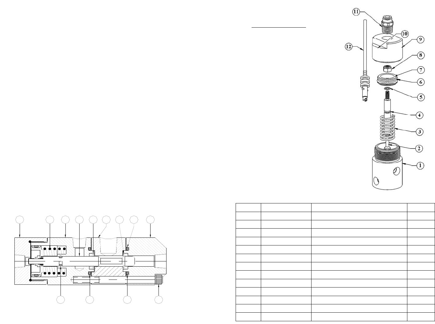
7. MAINTENANCE AND CLEANING:
Normally, purging the valve with an appropriate flushing material or solvent after
use is sufficient for cleaning. However, some material may cause a buildup in the
valve chamber, in this case periodic and thorough cleaning will be required.
CAUTION: Make sure fluid pressure is released before valve disassembly.
1. Release fluid pressure and disconnect fluid line.
2. Disconnect valve air line.
3. Remove end cap (1).
4. Pull out piston/spool assembly (4).
5. Remove the spring from air cylinder (2).
6. Remove socket head cap screws (10).
7. Separate material outlet block (9), material inlet block (6) and air cylinder
(3). Clean these parts if necessary.
8. Replace o-rings (13) on the spool shaft, material outlet block (8) and air
cylinder (12) if worn or damaged.
9. Remove lower seal (7) out of the outlet block and upper seal (5) out of the
air cylinder using a small screw driver.
10. Clean seal seats and carefully install new seals. It is important that seals
should be replaced in the same orientation to prevent leaks and accelerated
wear.
11. Lubricate O-rings with “Parker-O-Lube” or equivalent. Only the spool shaft
o-ring (13) should be lubricated with Bimba HT-99, or equivalent.
12. Assemble material outlet block (9), material inlet block (6) and air cylinder
(3).
13. Thread socket head cap screws into assembled valve (10). Tighten
uniformly to ensure correct valve alignment.
14. Insert the spring back into the air cylinder (2).
15. Insert piston/valve spool into valve body (4).
16. Install air fitting to end cap.
17. Install end cap to air cylinder (1). (HAND TIGHTEN ONLY)
Figure 5.0
7
8. SPARE PARTS
Valve Rear Section
ITEM PART NUMBER DESCRIPTION QTY
1* 934-000-001 Cylinder For TS934/TS941 1
1* 934A-000-001 Cylinder For TS934A/TS941A 1
2 934-000-005 Spool Shaft 1
3 934-000-006 Spring 1
4 TSD1400-008B Spool Shaft O-Ring, Viton 1
5 TSD1145-1 Fiber Washer 1
6 TSD1399-2 Piston U-Cup Seal 1
7 934-000-004 Piston 1
8 TSD1116-4 Lock Nut 1
9 927-000-007 End Cap 1
10 TSD1400-025A Cap O-Ring, Buna 1
11 TSD1002-26 Air Fitting, ¼'' Tube X ¼'' NPT 1
12 A0100268 Air Hose & Connector Assembly 1
Recommended lubricant:
“Parker-O-Lube”, or equivalent,
except item 4 (TSD1400-008B)
which requires Bimba HT-99, or
equivalent.
All O-Rings & seals must be
lubricated with the exception of
TSD400-69, which must remain
dry.