00195364-0102_Ext_Power_COT_D1_D2_D3_HF.pdf - 第21页
SIPLACE 2 External power supply unit for component trolleys from the SIPLACE D1/D2/D3/HF series 11/2006 Edition 21 2.4 Structure / settings 2.4.1 CAN bus interface The CAN bus interface is on the back of the device. When…
2 External power supply unit for component trolleys from the SIPLACE D1/D2/D3/HF series SIPLACE
11/2006 Edition
20
2
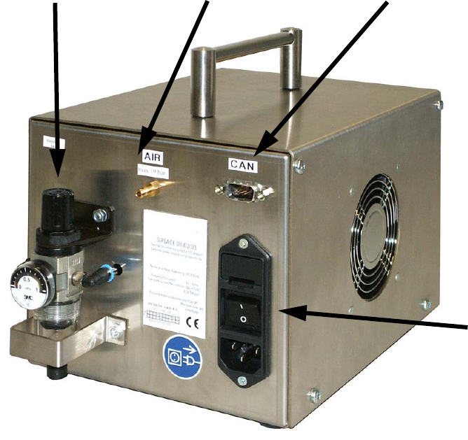
Fig. 3 External power supply unit for component trolleys, D1, D2, D3, HF series 03042437-01 (basic unit)
Combination
mains connector
Compressed air connection
CAN bus interface
Pneumatic unit
SIPLACE 2 External power supply unit for component trolleys from the SIPLACE D1/D2/D3/HF series
11/2006 Edition
21
2.4 Structure / settings
2.4.1 CAN bus interface
The CAN bus interface is on the back of the device. When used in conjunction with a set-up station
PC, this allows data to be exchanged between the PC and the component trolley. 2
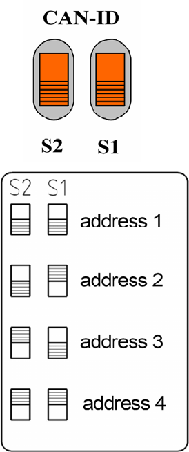
2.4.2 Setting the CAN bus address (location number)
2
2
2
2
Several power supplies (up to 4) may be connected to a
set-up station PC via a CAN bus cable.
On every device is connected, the CAN bus address must
be set using the two switches S1 and S2.
Each device must be given a different address.
Addresses must not be assigned more than once.
The setting should be made as shown below.
2 External power supply unit for component trolleys from the SIPLACE D1/D2/D3/HF series SIPLACE
11/2006 Edition
22
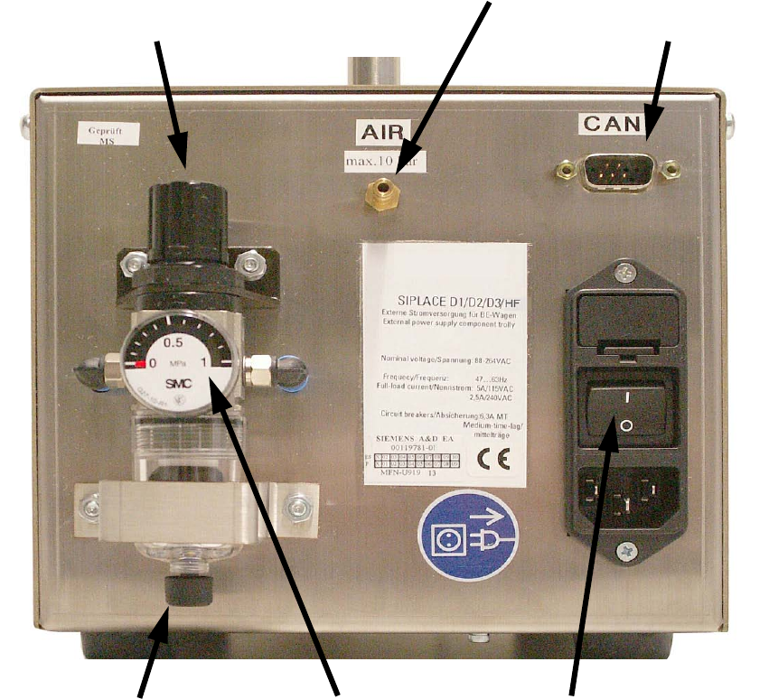
2.4.3 Pneumatic unit
The pneumatic unit consists of a pressure reducer, a manometer and a filter with condensate tank.2
The manometer displays the output pressure. 2
The output pressure is set by lifting and turning the adjusting cap. 2
2
Fig. 5 Back panel with pneumatic unit, etc.
Pressure reducer adjusting cap
Compressed air connection
CAN bus connection
Manual drain valve Power switchManometer