00195364-0102_Ext_Power_COT_D1_D2_D3_HF.pdf - 第26页
2 External power supply unit for component trolleys from the SIPLACE D1/D2/D3/HF series SIPLACE 11/2006 Edition 26 2.6.3 Changing the fuse 2 Fig. 7 Power switch with fuse s : Switch the power switch to OFF and make sure …
SIPLACE 2 External power supply unit for component trolleys from the SIPLACE D1/D2/D3/HF series
11/2006 Edition
25
2.6 Preventive maintenance
2.6.1 Compressed air filter
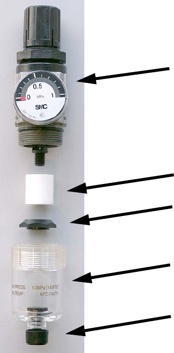
If the flow rate decreases severely, replace the microfilter (see picture below). 2
Release the quick-release coupling and detach it from the compressed air connection. Then un-
screw the condensate tank from the pressure reducer. When you turn down on the separating cap,
you can remove the microfilter. 2
Reverse the above sequence to insert the new microfilter. 2
2
Fig. 6 Compressed air filter unit
2.6.2 Condensate
The transparent condensate tank (see picture above) must be emptied before the condensate
level reaches the separating cap. To do this, turn the manual condensate drain knob to the left
(towards 0 <--). 2
Pressure-reducing valve
Microfilter
Separating cap
Knob for manually draining the condensate
Condensate tank
2 External power supply unit for component trolleys from the SIPLACE D1/D2/D3/HF series SIPLACE
11/2006 Edition
26
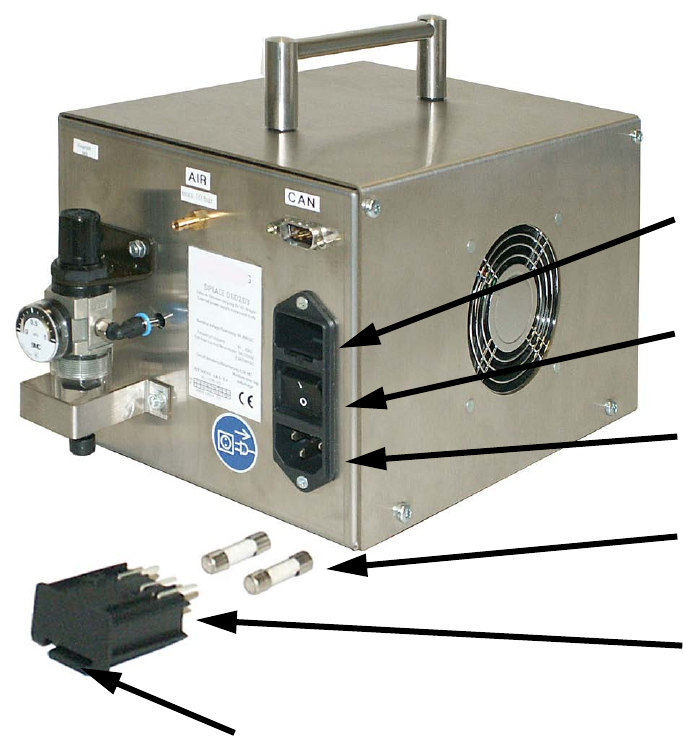
2.6.3 Changing the fuse
2
Fig. 7 Power switch with fuses
: Switch the power switch to OFF and make sure that the power plug is not plugged into the de-
vice connector.
: Release the snap closure of the fuse holder by pushing it up and pull the fuse holder and fuses
out of the drawer.
: Remove and check the two fuses and replace them if necessary.
: Only use type 5x20 mm / medium time-lag 6.3 Amp fuses (e.g. 03048168-01).
: Push the fuse holder with the two fuses back into the drawer until the snap closure latches.
Fuse holder
drawer
Power switch
Device plug
Fuses
Fuse holder
Snap closure

SIPLACE 2 External power supply unit for component trolleys from the SIPLACE D1/D2/D3/HF series
11/2006 Edition
27
2.7 Technical data
2.7.1 Compressed air
Input pressure: max. 10 bar (= 1000 kPa) 2
Output pressure: 2.5 bar (= 250 kPa) 2
2.7.2 Mains connection
2.7.3 Weights / dimensions
Weight: 4.3 kg 2
Dimensions: W x D x H = 180 x 360 x 210 mm 2
2
2
Voltage
88 - 264 VAC
Frequency
47...63 Hz
Rated current
5A / 115 VAC 2.5A / 230 VAC
Fuses
6.3A MT (medium time-lag)