SIPLACE X4 S micron X4i S micron.pdf - 第30页
30 SIPLACE Vision Component recognition Checking the component quality Recognizing the co llinearity of components Damaged or bent leads are recognized. Thi s helps avoi d solder-free connections du ring the subsequent s…

29
SIPLACE Vision
High placement performance and best quality
Board (substrate) recognition
In addition to the precise recognition of components, the PCB camera also guarantees reliable detec-
tion of inkspots and PCB fiducials.
Board recognition is used for:
• Position of fiducials for position recognition purposes
• Correction of elongation/compression
• Inkspot recognition
• Reading barcodes and data matrix codes
Nozzle measurement
• Type verification
• Nozzle concentricity
• Nozzle scan for contamination and wear
SmartPin Support
• Measurement of Smart Pins and their positions, plus constant monitoring during ongoing operations
Optional functions
• Teaching and recognizing OSC-THT (OSC package) see page 36.
• SIPLACE Vision teaching station
Separately from ongoing production, the SIPLACE Vision Teaching Station facilitates quick and
easy offline generation of component shape descriptions, even for complex components.
30
SIPLACE Vision
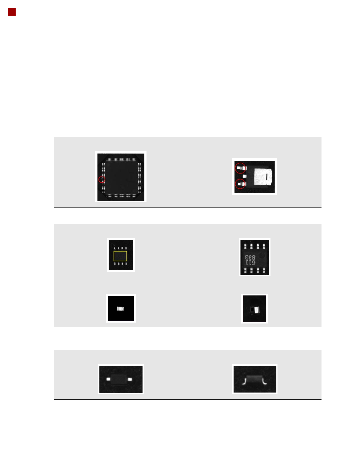
Component recognition
Checking the component quality
Recognizing the collinearity of components
Damaged or bent leads are recognized. This helps avoid solder-free connections during the subsequent solder-
ing process.
Damaged leads Damaged leads
Recognizing flipped (face down) or upright components
Both chip and IC component shapes (e.g. SOT) recognized in flipped (turned face down) or upright state.
SOT OK SOT “face down”
Flipped chip Chip upright
Checking the lead width
The optical checking of the lead width recognizes tilted or damaged leads. This helps to recognize e.g. diodes
with tilted leads.
Lead width OK Tilted lead
31
SIPLACE Vision
Component recognition
Checking the component quality
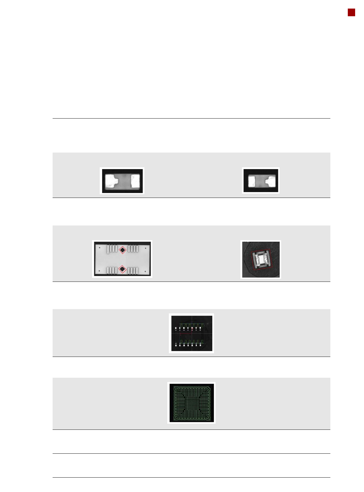
Checking the lead length
The lead length check determines whether the leads have been distorted. This inspection is possible by checking
whether leads of the same type e.g. chip shapes have different lengths. Flipped and rotated components can also
be detected.
Component OK in this position Rotated
Detecting special shapes with rectangular functions
When using certain special component shapes, it is sometimes necessary to program parts on the components or
outlines as rectangular shapes. This ensures that they can be processed more reliably.
Rectangular function on the component Rectangular component with irregular edges
Detecting incorrect component descriptions
The Vision system checks whether the position of the component corresponds to the measured Vision data. The
following example has more leads than were programmed in the component shape description.
Teaching complex BGA structures
Complex BGA structures can be taught within only a few seconds.
Placing when inkspot is not present
A fiducial can now be defined for the omission of panels. If a fiducial is found (cross, circle, etc.), this panel will be
omitted.
Checking the inner area of circular fiducials
To differentiate circular fiducials from other structures on the board, a brightness check is performed in the inner
area of these fiducials.