222085 Issue 1 - Horizon APiX Appendix Manual.pdf - 第26页
INSTALLATION APPENDIX SAFETY FEATURES Chapter Issue 1 June 15 Appendix to Micron Technical Manuals 2.7 Pneumatic Lockout W ARN ING COMPRESSED AIR . COMPRESSED AIR SH OULD NEVER IMPINGE UPON THE BODY . PORTS, P IPES, ETC …
INSTALLATION APPENDIX
SAFETY FEATURES
2.6 Appendix to Micron Technical Manuals Chapter Issue 1 June 15
centre section of the switch.
5. This completes the electrical lockout.
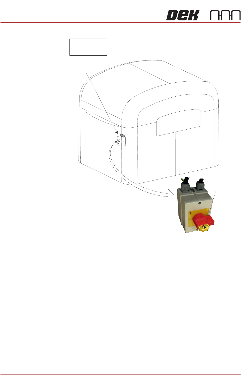
Mains Isolator
Switch
NOTE
Switch shown in
the OFF position
View on Front of Machine
Lockout
Point
INSTALLATION APPENDIX
SAFETY FEATURES
Chapter Issue 1 June 15 Appendix to Micron Technical Manuals 2.7
Pneumatic Lockout
WARNING
COMPRESSED AIR. COMPRESSED AIR SHOULD NEVER IMPINGE UPON THE
BODY. PORTS, PIPES, ETC MUST NEVER BE BLOCKED BY HAND. BEFORE
CONNECTING OR DISCONNECTING ANY PNEUMATIC COMPONENTS, ENSURE
THE COMPRESSED AIR SUPPLY HAS BEEN DISSIPATED AND DISCONNECTED
FROM THE MACHINE.
Pneumatic lockout of the machine is achieved by:
NOTE
If the electrical lockout procedure has just been implemented, go to Step 3.
1. Close down the machine software.
2. Switch the electrical mains isolator to the OFF position.
3. Turn OFF and lockout the factory’s main pneumatic supply to the machine.
4. Pressurised air remaining in the pneumatic supply line is vented via the
pneumatic dump valve.
5. Raise the rear printhead cover.
6. Remove the rear panel and check the mains regulator gauge to confirm all
pressurised air has been vented.
7. Disconnect the pneumatic supply line from the machine.
8. This completes the pneumatic lockout.
INSTALLATION APPENDIX
SEMI - LEVELS OF ELECTRICAL WORK
2.8 Appendix to Micron Technical Manuals Chapter Issue 1 June 15
SEMI - LEVELS OF ELECTRICAL WORK
The table below show the four levels of energized electrical work carried out on
electrical equipment and its associated circuits, as defined by the SEMI S2-
0712 Standard.
Throughout all the ASM manuals when a maintenance or calibration procedure
falls within any of these four levels of energized electrical state, the appropriate
symbol is represented in the margin alongside that procedure.
A full definition can be found in the SEMI S2-0712c Safety Guidelines for
Semiconductor Manufacturing Equipment. See also NFPA 79-14.3, IEC/
EN60204-1, BS EN60950-1 and IEC/EN 60950-1.
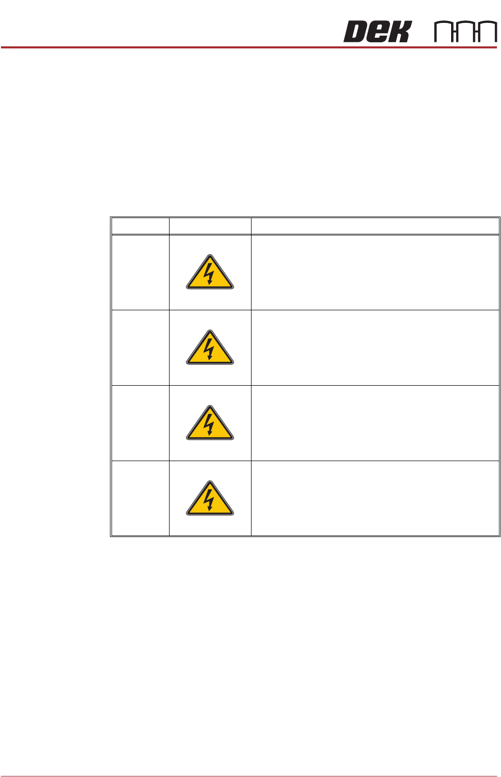
Type Symbol Definition
1 Equipment is fully de-energized
2 Equipment is energized. Energized circuits are covered or
insulated. Work is performed at a remote location to pre-
clude accidental shock
3 Equipment is energized. Energized circuits are exposed and
accidental contact is possible. Potential exposures are less
than 30 volts rms, 42.4 volts peak to peak, 60 volts dc, or 240
volt-amps in dry locations
4 Equipment is energized. Energized circuits are exposed and
accidental contact is possible. Potential exposures are
greater than 30 volts rms, 42.4 volts peak to peak, 60 volts
dc, 240 volt-amps in dry locations, or radio frequency (rf) is
present
SEMI 1
SEMI 2
SEMI 3
SEMI 4