Process Lens PL Service Manual_EN.pdf - 第127页
3 Replacing spare parts Se rv ic e Ma nu al P ro ce ss L en s PL - 0 3/ 20 25 12 7 Fig.181: Lifting table motor 1. Stopper screw 2. Cam 3. Screw A ► Unscrew screw A (3) from the cam (2) using an Allen key size 5.0. ► …
3 Replacing spare parts
126 Service Manual Process Lens PL - 03/2025
3.5.2.5 Changing the motor of the lifting table
Parts
03064983-xx BLDS motor with PLG and brake
Equipment and tools
●
Allen key size 5.0
Requirements
●
Machine is switched off.
Remove the motor of the lifting table
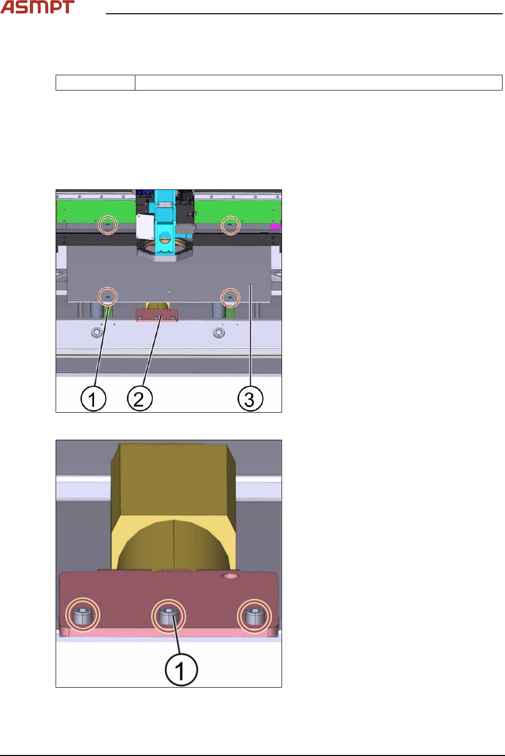
Fig.179: Lifting plate
1. Screw (4 x)
2. Motor of the lifting table plate
3. Lifting table plate
► Unscrew the screws(1) off the lifting table
plate(3) using an Allen key size 5.0.
► Remove the lifting table plate(3).
► Disconnect all connectors from the
TSP400.
Fig.180: Lifting table motor
► Unscrew the 3 screws(1) off the lifting
table motor using an Allen key size 5.0.
3 Replacing spare parts
Service Manual Process Lens PL - 03/2025 127
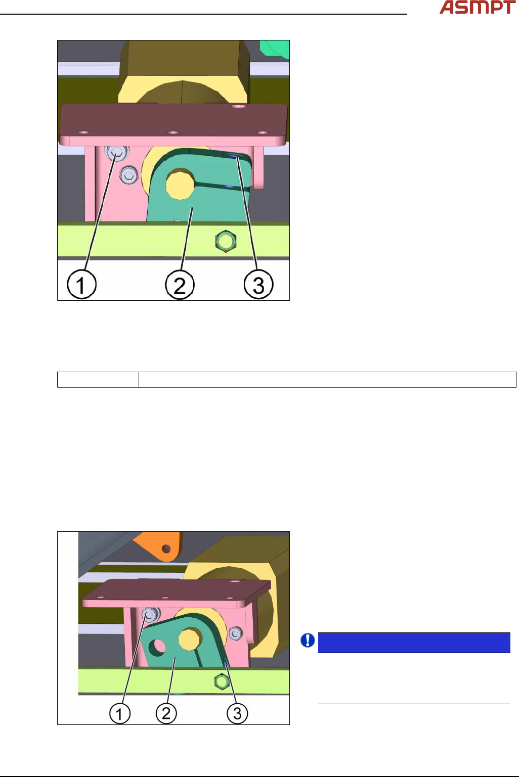
Fig.181: Lifting table motor
1. Stopper screw
2. Cam
3. Screw A
► Unscrew screw A(3) from the cam(2)
using an Allen key size 5.0.
► Remove the motor.
Replace the motor of the lifting table
Parts
03064983-xx BLDS motor with PLG and brake
Equipment and tools
●
Allen key size 5.0
Requirements
●
Machine is switched off.
●
The motor of the lifting table is dismantled.
●
The lifting table plate is dismantled.
► Position the lifting table motor.
► Connect the connectors at the TSP400.
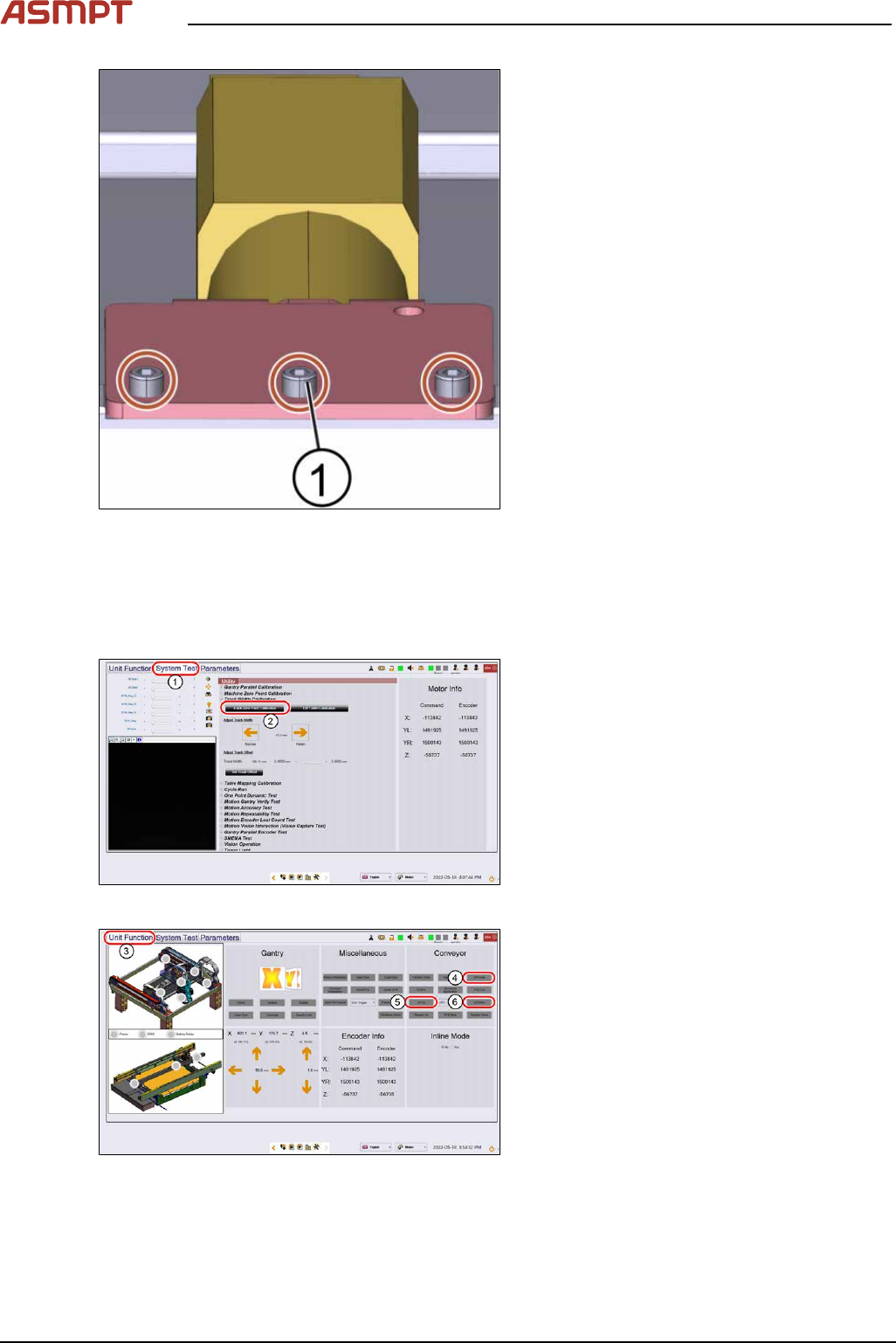
Fig.182: Lifting table motor
1. Stopper screw
2. Cam
3. Screw A
► Put the cam(2) in the right position so that
the cam hits the stopper screw(1). Fasten
the screw of the cam using an Allen key
size 5.0.
NOTICE!
Positioning of the cam
The cam must be in the position as shown
in the picture when the screw is tightened.
It must hit the stopper screw.
.
3 Replacing spare parts
128 Service Manual Process Lens PL - 03/2025
Fig.183: Lifting table motor
► Fasten the 3 screws(1) off the lifting table
motor using an Allen key size 5.0.
► Put the lifting table plate back on.
► Fasten the four screws of the lifting table
plate using an Allen key size 5.
► Check the function of the table go to sec-
tion 3.5.2.5.2 "Check the function of the
motor of the lifting table" [}128].
Check the function of the motor of the lifting table
Requirements
●
Machine is switched on.
Fig.184: “System Test” tab
► Open the Diagnostic page.
► Go to the tab System Test(1).
► Click on the button Track zero point cali-
bration(2).
► A message will indicate that the calibration
was successful.
Fig.185: “Unit function” tab
► Go to the tab Unit function(3).
► Proceed to the conveyor section and press
the buttons Lift Home(4), Lift up(5) and
Lift down(6) to check the function of the
lifting table.
► On screen messages will confirm the suc-
cessful function test of the lifting table.
► If the conveyor system does not move or
any fault message occurs, the conveyor
system needs to be adjusted.