Process Lens PL Service Manual_EN.pdf - 第39页
3 Replacing spare parts Se rv ic e Ma nu al P ro ce ss L en s PL - 0 3/ 20 25 39 Fig.38: “Finished” Message ► Click on OK . The DLP module is now running the latest version. 3.2 Vision module HD 3.2.1 Optical head 3.2.1…
3 Replacing spare parts
38 Service Manual Process Lens PL - 03/2025
3.1.2.5 Upgrading the firmware of the DLP module
When the firmware of the DLP module is not running the latest firmware, it needs to be updated.
Requirements
●
Machine is switched on.
●
The .rbf file is downloaded from the ASMPT internal website.
Upgrading the firmware
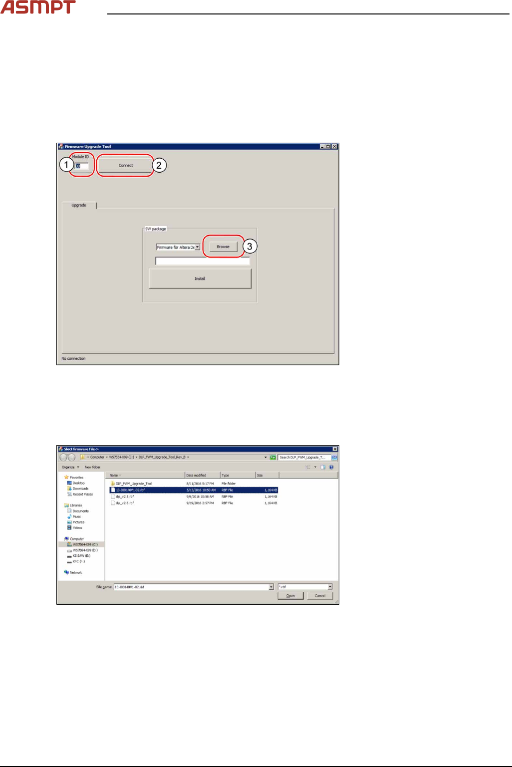
Fig.36: Browsing for the *.rbf file
► Open the DLP firmware upgrade software on the computer.
► In the Module ID input field(1) enter the number "00" for the left DLP module or "01" for the right
DLP module to test the left or the right DLP module and click on Connect(2).
► Click on the browse button(3) to browse to the needed *.rbf file.
Fig.37: Searching the needed file
► Double-click on the needed .rbf file.
► Click on the install button to install the latest version.
3 Replacing spare parts
Service Manual Process Lens PL - 03/2025 39
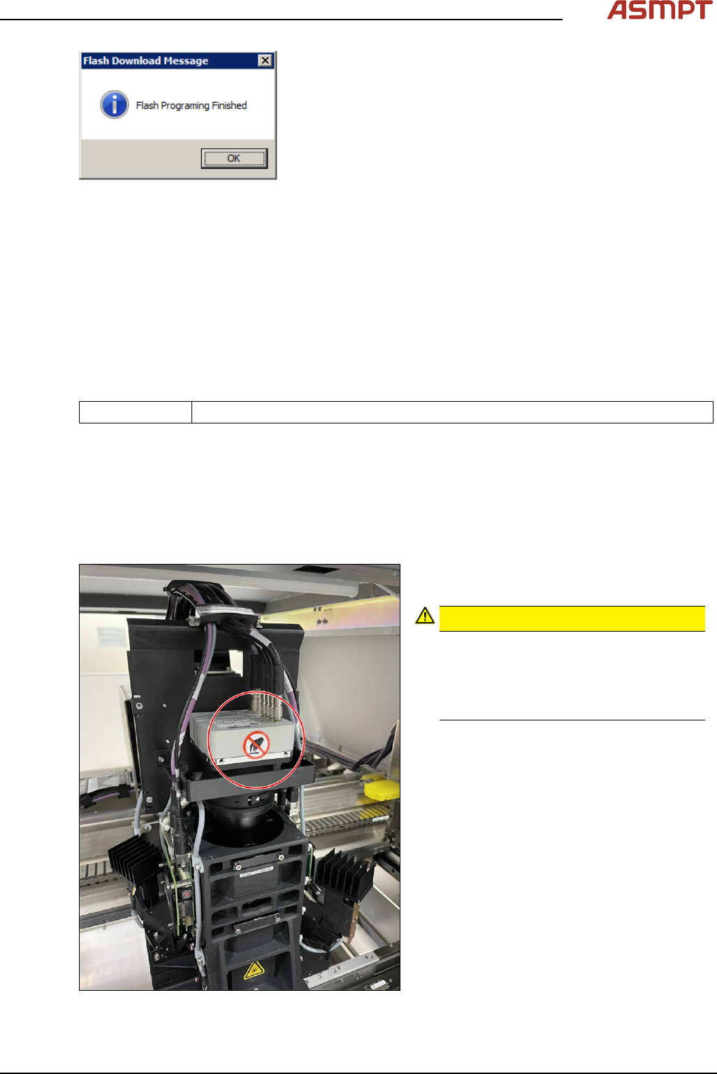
Fig.38: “Finished” Message
► Click on OK.
The DLP module is now running the latest version.
3.2 Vision module HD
3.2.1 Optical head
3.2.1.1 Replacing the optical head
Parts
03251058-xx HD Vision Module Kit
Equipment and tools
●
Allen key size 2.5
Requirements
●
Machine is switched off.
Removal
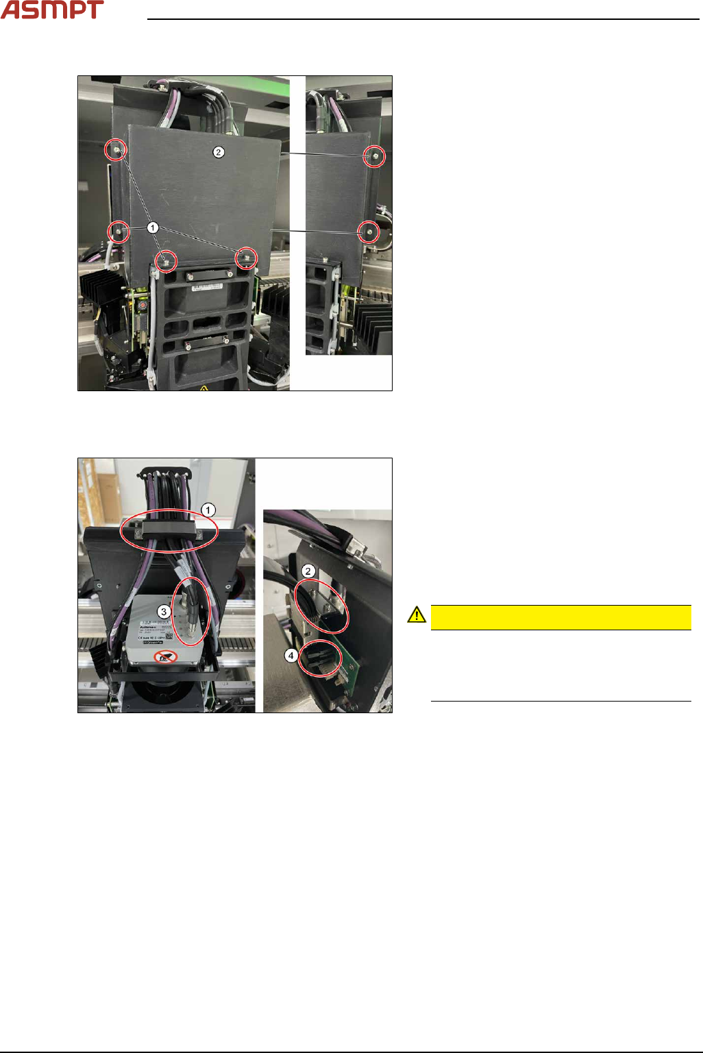
Fig.39: Moving the optical head to the middle of the
machine
► Move the optical head carefully to the
middle of the machine.
CAUTION!
Sensitive camera system
The camera system is very sensitive and
must therefore not be touched.
Make sure you don’t touch the camera
when moving the gantry.
.
3 Replacing spare parts
40 Service Manual Process Lens PL - 03/2025
Remove cover
Fig.40: Removing the cover
► Remove the cover(2) that protects the
connection spots for the cables by remov-
ing the six screws(1) by using an Allen
key size 2.5.
► Place the dismantled cover on a service
table.
Remove cables
Fig.41: Removing cable clamps and connectors
► Remove the cable clamp(1) that fixes the
cables by unscrewing the two screws
using an Allen key size 2.5.
► Remove the cable clamp (2) that fixes the
cables by unscrewing the two screws
using an Allen key size 2.5.
► Unscrew 5x cables (3) and unplug 2xrib-
bon cable connectors (4)
CAUTION!
Sensitive camera system
The camera system (3) is very sensitive.
Therefore do not touch the camera sys-
tem to avoid damage to it.
.
► Carefully put the cables aside.