Infinity High Throughput Conveyor Module.pdf - 第33页
INFINITY +,*+7+ 528*+387&2 19(<2502' 8/( $'-8670 (176$1 '6(77,1* 6 Chapter Issue 1 May 03 Technical Reference Manual 15.33 measurement. 5. On completion, carr y out Front Auxili ary Conveyor Ra…
INFINITY
+,*+7+528*+387&219(<2502'8/(
$'-8670(176$1'6(77,1*6
15.32 Technical Reference Manual Chapter Issue 1 May 03
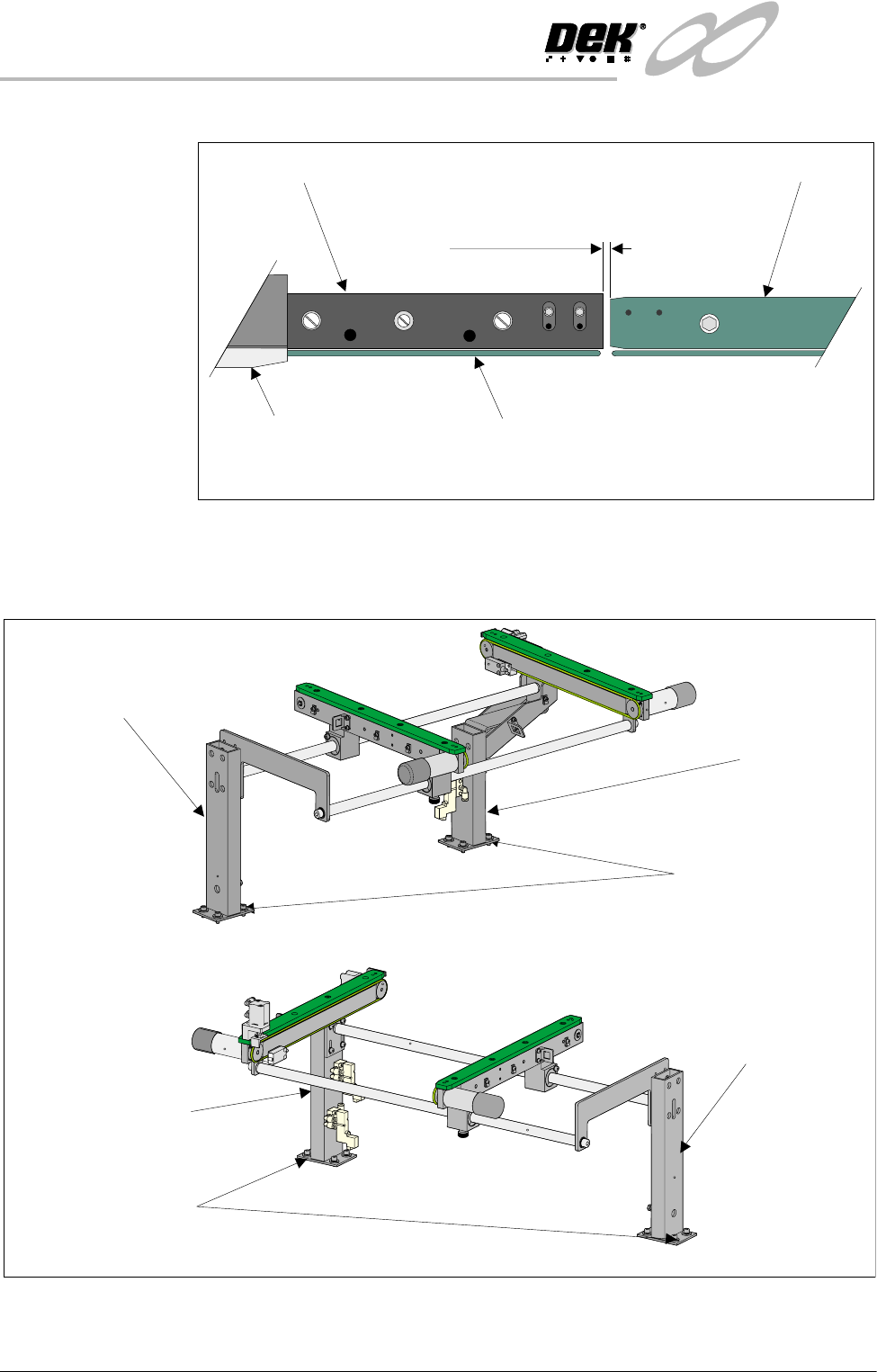
print station and the auxiliary conveyors (in four positions) is 3.0 ± 0.5mm.
2. If adjustment is required, loosen the eight auxiliary conveyor rail support
securing bolts (four bolts on each support) that secure the auxiliary conveyor
to the machine lower frame.
3. Adjust the position of the conveyor to obtain the 3.0 ± 0.5mm gap.
4. Re-tighten the securing bolts disturbed in Step 2 and re-check the gap
Board Clamp
Board Transport Rail
Auxiliary Conveyor
Print Station
Plan View on Print Station and Auxiliary Rails
5157438
3.0mm +/- 0.5mm
Rear View of Left Auxiliary Conveyor
Front Auxiliary Conveyor
Rail Support
Rear Auxiliary Conveyor
Rail Support
Rail Support to
Main Frame Bolts
(4 off in 2 positions)
Rear View of Right Auxiliary Conveyor
Front Auxiliary Conveyor
Rail Support
Rear Auxiliary Conveyor
Rail Support
Rail Support to Main Frame
Bolts (4 off in 2 positions)
INFINITY
+,*+7+528*+387&219(<2502'8/(
$'-8670(176$1'6(77,1*6
Chapter Issue 1 May 03 Technical Reference Manual 15.33
measurement.
5. On completion, carry out Front Auxiliary Conveyor Rail Parallelism check.
Auxiliary Conveyor
Levelling
To check and if required adjust the levelling of the auxiliary conveyors, carry out
the following procedure:
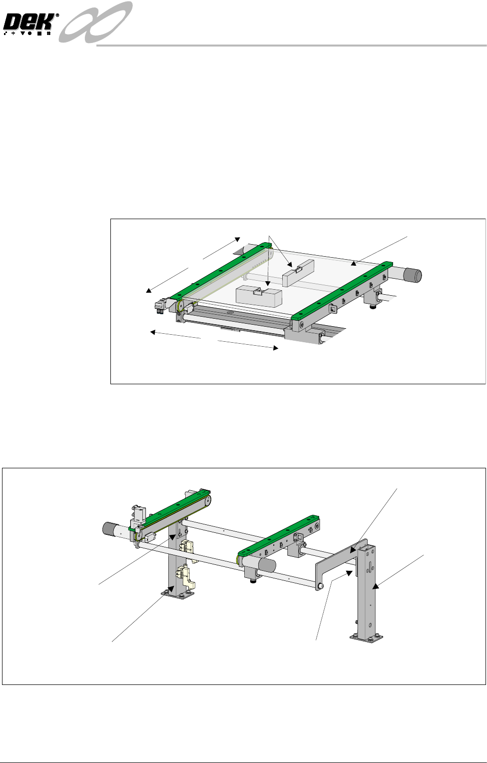
1. Adjust the auxiliary conveyor rail width to approximately 250mm.
2. Place a Board Clamp Setting Plate Pt No 140403 onto the auxiliary conveyor
transport belts.
3. Place a spirit level on top of the setting plate and check the levelness of the
conveyor in the X and Y planes.
4. If adjustment is required, carry out the following:
a. Loosen the four bolts that secure the auxiliary conveyor shaft guide plate
to the rear rail support and the four bolts that secure the rail bracket to
front rail support.
b. Carefully adjust the height of the auxiliary conveyor rails to achieve
conveyor levelness.
c. Re-tighten the rail bracket and shaft guide plate securing bolts and repeat
the check.
X
Y
Board Clamp
Setting Plate
View on Auxiliary Conveyor
Spirit Level
Rear View of Right Auxiliary Conveyor
Front Auxiliary Conveyor
Rail Support
Rear Auxiliary Conveyor
Rail Support
Shaft Guide Plate
Shaft Guide Plate to Rear
Rail Support Bolts (4 off)
Rail Bracket to Front
Rail Support Bolts
(in 4 positions)
INFINITY
+,*+7+528*+387&219(<2502'8/(
$'-8670(176$1'6(77,1*6
15.34 Technical Reference Manual Chapter Issue 1 May 03
Auxiliary Conveyor Rail Parallelism
WARNING
BOARD CLAMPS. EXTREME CARE MUST BE EXERCISED WHEN WORKING IN
THE TOOLING AREA OF THE MACHINE TO AVOID INJURY. THE FOILS ON THE
FRONT AND REAR BOARD CLAMPS ARE VERY SHARP.
Front Rail To check and if required adjust the auxiliary conveyors front rail parallelism,
carry out the following procedure at transport height:
NOTE
The parallelism of the auxiliary conveyors rails is dependent on the front and
rear print station rails being parallel. Therefore, before any adjustment is carried
out an assessment of the parallelism of the print station rails must be carried out.
1. In Rail System Diagnostics, select Adjust and alter board width to 250mm.
2. Select Drive Rail to Board Width. The rails are driven to the board width
selected.
3. Adjust the both auxiliary conveyor rail widths to approximately 250mm.
4. Place one of the Board Clamp Setting Plates Pt No 140403 onto the print
station transport belts.
5. Manually slide the setting plate back and forth from the print station to the
right hand auxiliary conveyor, ensuring the plate moves freely without
binding or jamming.
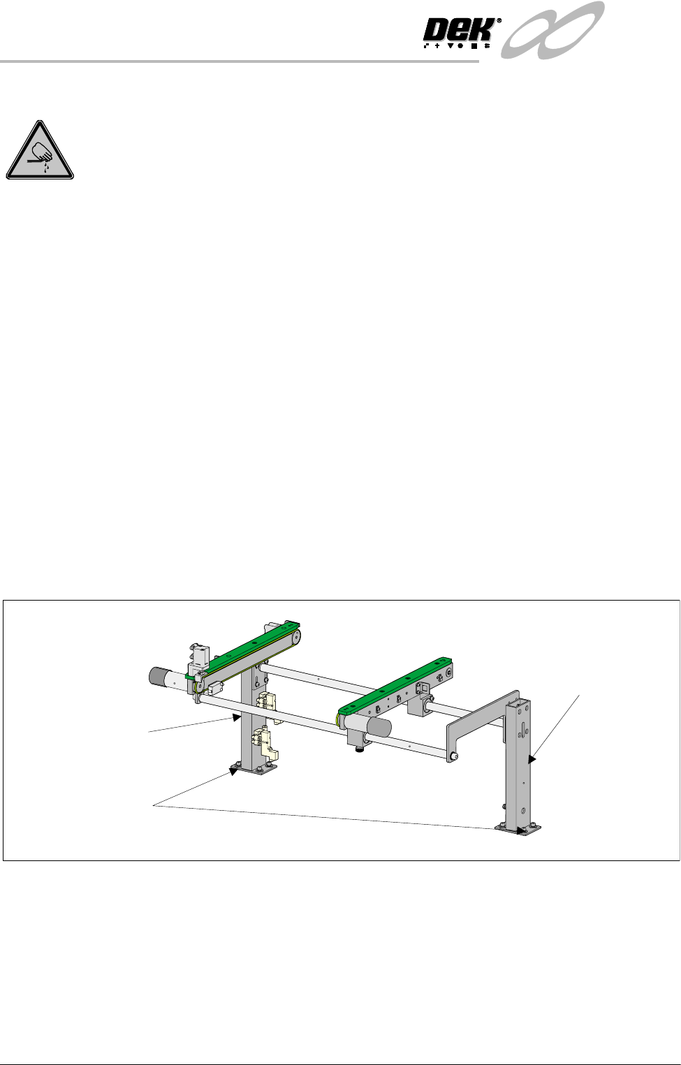
6. If adjustment is required on the right hand auxiliary conveyor, loosen the
eight auxiliary conveyor rails support securing bolts (four on each support)
that secure the auxiliary conveyor to the machine lower frame.
7. Carefully adjust the conveyor to obtain front rail parallelism with the print
station front rail, whilst maintaining the gap between the auxiliary rail and
print station rail (refer to Auxiliary Rail to Print Station Gap section of this
chapter).
8. Re-tighten the securing bolts and re-check for parallelism.
9. Repeat Steps 5 - 8 for the left hand auxiliary conveyor.
Rear View of Right Auxiliary Conveyor
Front Auxiliary Conveyor
Rail Support
Rear Auxiliary Conveyor
Rail Support
Rail Support to Main Frame
Bolts (4 off in 2 positions)