Infinity High Throughput Conveyor Module.pdf - 第43页
INFINITY +,*+7+ 528*+387&2 19(<2502' 8/( $'-8670 (176$1 '6(77,1* 6 Chapter Issue 1 May 03 Technical Reference Manual 15.43 Rail Shock Absorber Setting 1. Ensure the machine is powered down. 2. …

INFINITY
+,*+7+528*+387&219(<2502'8/(
$'-8670(176$1'6(77,1*6
15.42 Technical Reference Manual Chapter Issue 1 May 03
Home Position Rail
Width Check
1. In Diagnostics, select Rail System and Select Module.
2. Select Home Rail Width and Run Diagnost.
3. Select Adjust and set board width to 250mm.
4. Select Drive Rail to Board Width.
5. Select Run Diagnost.
6. Check that the board clamp width is between 250.35mm - 250.55mm.
7. Check that the mid rail width is between 250.35mm - 250.65mm.
8. Check that the rail end green insert width is between 250.35mm -
250.85mm.
NOTE
If any of the rail widths are out of tolerance do not adjust the rails, adjust the
position of the rail home position sensor and recheck.
9. Using a suitable test board, with the rail width programmed to the board size,
select Cycle Board on Belts.
10.Select Run and ensure the board runs through the entire length of the rail
system for 10 complete cycles, without jamming or excessive clicking of the
board edges.
NOTE
If any jamming occurs investigate the position of the board/snugger clamps, mid
rails and the green inserts at the rail ends before repeating the check.
INFINITY
+,*+7+528*+387&219(<2502'8/(
$'-8670(176$1'6(77,1*6
Chapter Issue 1 May 03 Technical Reference Manual 15.43
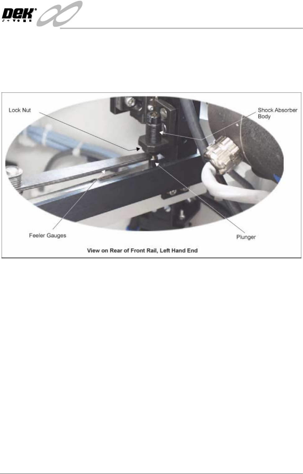
Rail Shock
Absorber Setting
1. Ensure the machine is powered down.
2. Using feeler gauges, check that a gap of 2.5mm - 3mm exists between the
top of the plunger and the shock absorber body. Alternatively use a 2.5mm
and 3mm allen key as a Go, No Go Gauge.
3. Repeat Step 2 for the three other rail shock absorbers.
4. If adjustment is necessary, slacken the lock nut.
5. Rotate the shock absorber body as required, clockwise to reduce the gap,
anti-clockwise to increase the gap.
6. Check the gap is between 2.5mm - 3mm.
7. Repeat Steps 5 and 6 until the correct dimension is achieved
8. Tighten the lock nut.
9. Recheck the gap is still within limits.
Reversing Throughput Direction
To change the direction of throughput of the machine, carry out one of the
following two procedures:
Right to Left
Configuration
To change the configuration of the machine from Left to Right to Right to Left
throughput carry out the following:
1. If required, raise the head and insert the head prop.
2. Power down the machine and disconnect the quick release pneumatic
connection at the machine’s external services panel
3. Gain access to the left hand auxiliary conveyor sensor.
4. Remove the two sensor securing screws and remove the sensor from the
mounting bracket.
5. Remove the two bolts securing the sensor mounting bracket to the front
INFINITY
+,*+7+528*+387&219(<2502'8/(
$'-8670(176$1'6(77,1*6
15.44 Technical Reference Manual Chapter Issue 1 May 03
conveyor rail.
6. Refit the mounting bracket to left hand conveyor front rail using the outer-
most bracket mounting holes and refit the sensor removed in Step 4 to the
mounting bracket.
7. Identify the right hand auxiliary conveyor sensor, remove the two sensor
securing screws and remove the sensor.
8. Remove the two bolts securing the sensor mounting bracket to the front
conveyor rail.
9. Refit the mounting bracket to right hand conveyor front rail using the
innermost bracket mounting holes and refit the sensor removed in Step 7 to
the mounting bracket.
10.Identify the downline conveyor board stop fitted to the right hand auxiliary
conveyor.
11. Disconnect the two 4mm pneumatic pipes feeding the conveyor board stop.
12.Remove the pneumatic elbow connectors to gain access to the two 3mm
allen screws securing the board stop bracket to the conveyor rail.
Left Hand
Auxiliary Conveyor
Right Hand
Auxiliary Conveyor