Infinity High Throughput Conveyor Module.pdf - 第5页
INFINITY +,*+7+ 528*+387&2 19(<2502' 8/( 0(&+$ 1,&$/'( 7$,/ Chapter Issue 1 May 03 Technical Reference Manual 15.5 MECHANICAL DET AIL T ransport Belt Motors The transport belt motors drive th…
INFINITY
+,*+7+528*+387&219(<2502'8/(
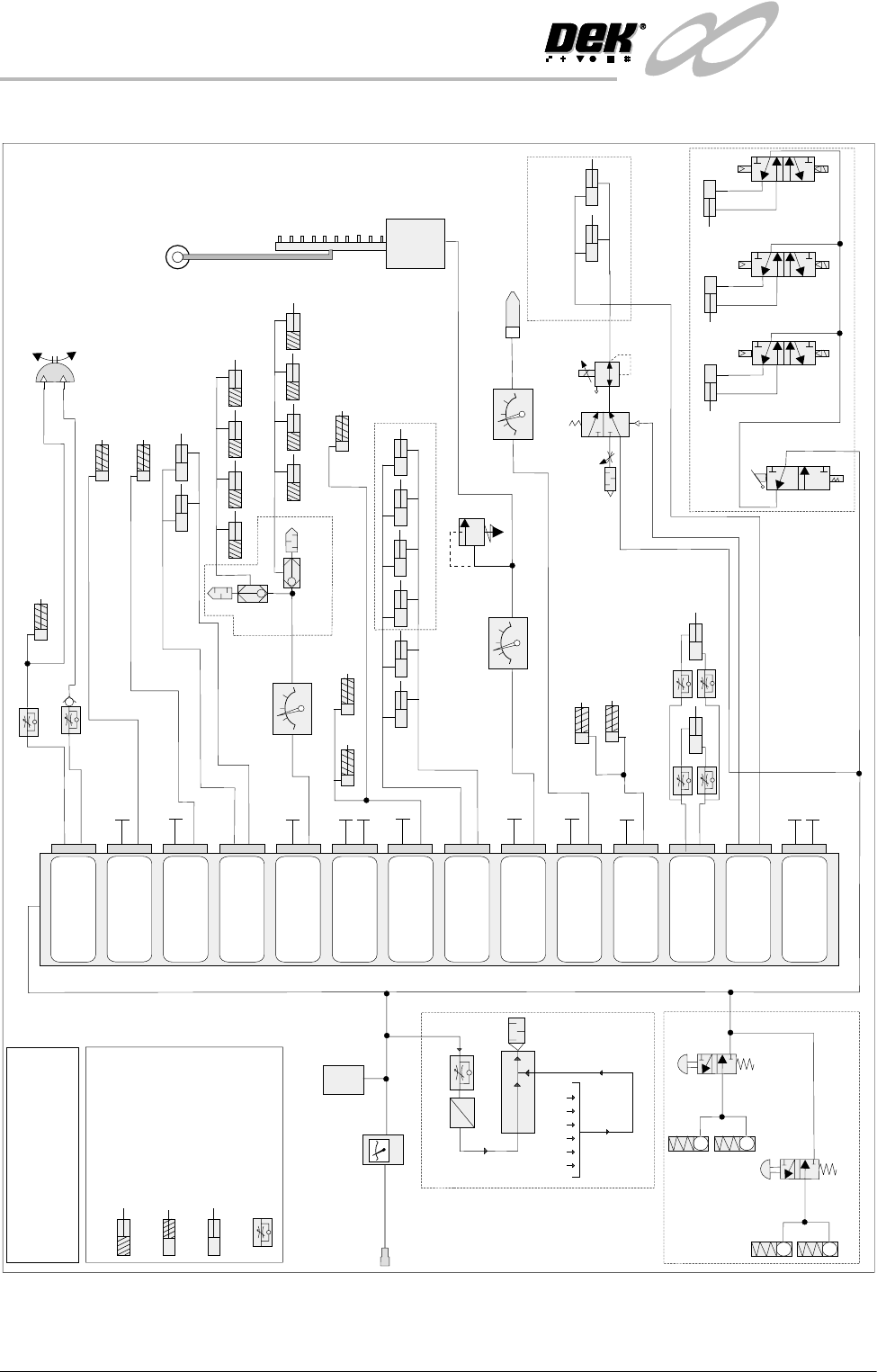
31(80$7,&6&+(0$7,&
15.4 Technical Reference Manual Chapter Issue 1 May 03
PNEUMATIC SCHEMATIC
Remote Board Stop
(optional)
A = Signal to Switch
B = Live
*
NOTE
Each solenoid has two parts A and B
Double Acting Cylinder
KEY
Single Acting Cylinder
(Piston retracted at rest)
Single Acting Cylinder
(Piston extended at rest)
Speed Control Valve
Vortex Cleaner Lift
(optional)
Screen Clamps
Pressure Relief Valve
(Infinity Only)
Pressure Regulator
Suction and
Filtration Unit
Underscreen
Cleaner
(optional)
Solvent
Tank
A
B
A
B
A
B
A
B
A
B
Board Stop
Screen Drive
Couple Left
(Infinity Only)
Screen Drive
Couple Right
(Infinity Only)
Screen Drive
Couple Rear
(Infinity Only)
Board Clamps
Spare
Cleaner Sqy Bar
Screen Clamps
Tank Pressure
Paste Dispense
Lid Bolt
Lid Bolt
ProFlow
(optional)
Autoflex
(optional)
High Throughput Conveyor Option
High Thro’put
Conveyor Option
Paste Dispenser
(optional)
Pressure Regulator
ProFlow - SCAR
Manifold
A
B
A
B
A
B
A
B
A
B
Lid Bolt
Autoflex
(Infinity Only)
ProFlow
SCAR
Spare
Screen Clean Squeegee Bar
(optional)
Board Clamps
A
B
Camera Board Stop
See Note
*
Screen Drive Couple Left
Screen Drive Couple Right
Screen Drive Couple Rear
Pressure Regulator
(optional)
A
B
A
B
A
B
Vacuum Tooling
Vacuum Tooling (optional)
Web Assembly
Locking Cartridge
Non Latching
Manual Valve
ASM Option (Horizon Only)
Filter
Regulator
Assembly
Mains Air
Connection
5 bar (min)
Pressure
Sensor
INFINITY
+,*+7+528*+387&219(<2502'8/(
0(&+$1,&$/'(7$,/
Chapter Issue 1 May 03 Technical Reference Manual 15.5
MECHANICAL DETAIL
Transport Belt
Motors
The transport belt motors drive the ‘O’ ring type transport belts which transport
the board through the machine. Each rail section has its own motor and
transport belt.
The auxiliary rail motors (4 positions) incorporate a 14:1 ratio gearbox allowing
belt speeds of approximately 500mm/sec (30m/min).
The print station rail motors (2 positions) incorporate a 4.8:1 ratio gearbox
allowing belt speeds of up to 1000mm/sec (60m/min).
NOTE
For belt speed calibration refer to the Calibration section of this chapter.
Conveyor Board
Stops
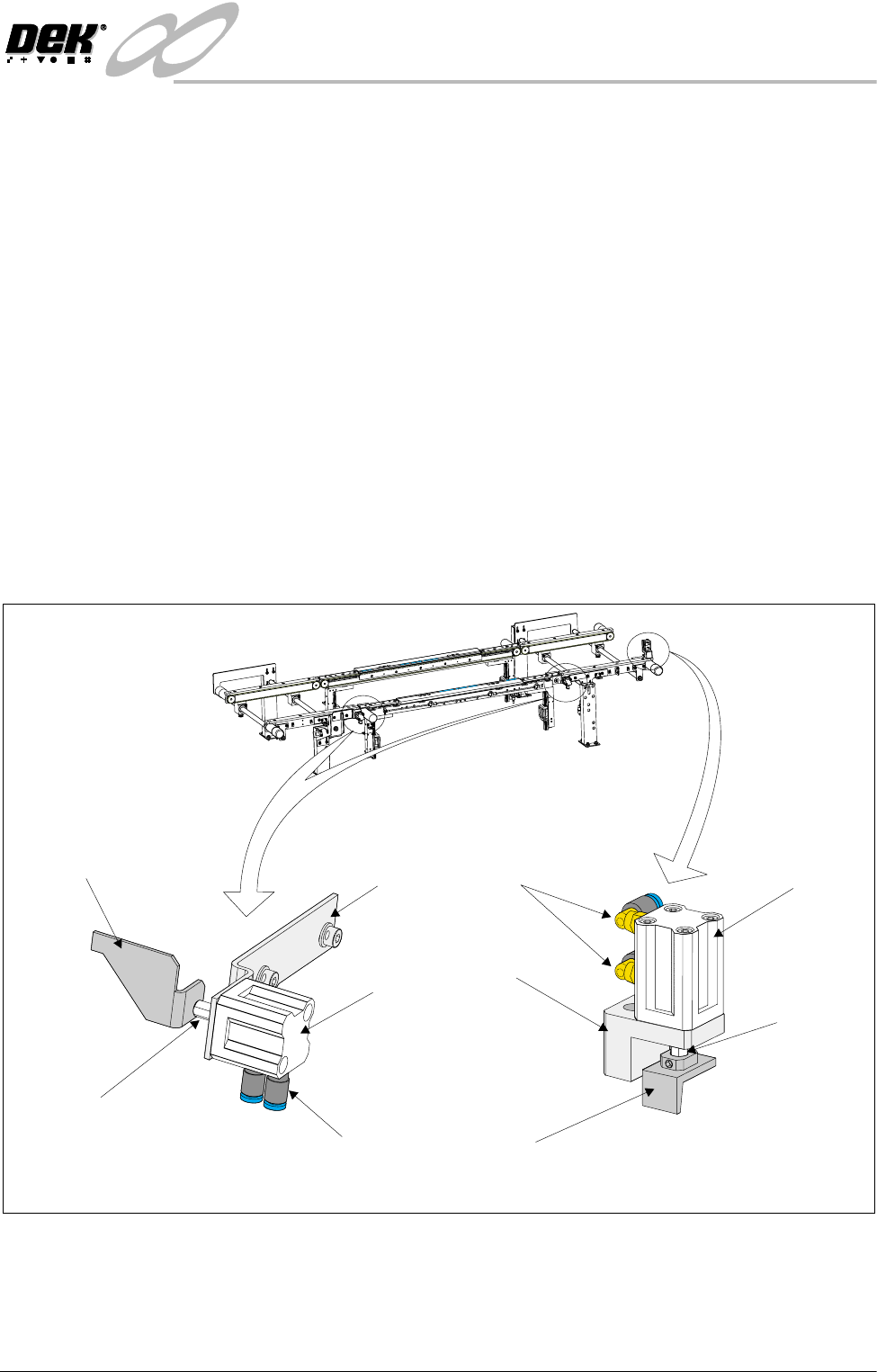
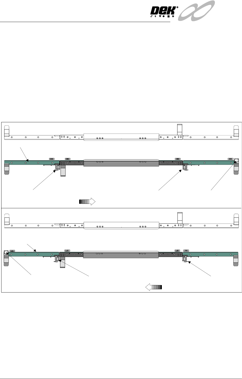
There are two types of pneumatically operated double acting cylinders fitted as
board stops to the high throughput conveyor module in three positions. The
print station and upline board stop cylinders are identical, the downline board
stop differs only in the length of stroke of the piston. These may be orientated
in one of two configurations, left to right board feed or right to left board feed.
The figure overleaf shows the positions for the board stops in either configura-
tion.
Figure 15-2 Conveyor Board Stops
Two are located at either end of the configured downline auxiliary conveyor, one
is located at the downline end of the upline conveyor.
The designated print station board stop is activated by the downline auxiliary
Double Acting
Cylinder
Double Acting
Cylinder
Pneumatic
Connections
Pneumatic
Connections
Securing
Bracket
Securing
Bracket
Board Stop
Bracket
Board Stop
Bracket
Pneumatic
Piston
Pneumatic
Piston
Downline Conveyor Board Stop
Upline/Print Station Conveyor Board Stop
INFINITY
+,*+7+528*+387&219(<2502'8/(
0(&+$1,&$/'(7$,/
15.6 Technical Reference Manual Chapter Issue 1 May 03
conveyor controller, thus preventing a board leaving the print station conveyor
whilst a board is still on the downline auxiliary conveyor. (Or when a transfer
between the downline conveyor and the downline machine is taking place.)
Each board stop is activated by the ‘Downline available’ FMI signal from the
section/machine downline of it, thus preventing a board from leaving the
conveyor until the section/machine asks for it.
CAUTION
CONVEYOR BOARD STOP.
Conveyor board stops may be damaged by the
printing of heavy boards, thus preventing the overshoot of these boards.
To minimise this effect, adjust the position of the relevant board stop
sensor if damage to the conveyor board stops occur (refer to Adjustments
and Settings section of this chapter).
Figure 15-3 Board Stop Positions
Moving Rail Print
Station
The moving rail print station is transported into position, as set by the board
width parameter in the current product file, by two drive shafts. A single stepper
motor drives the right hand drive shaft via a drive belt. Transmission between
the two drive shafts is achieved via pulleys and a drive belt.
The moving print station houses four pneumatic cylinders, two of which, are
used to operate the board clamps to secure the board against the transport belt
and the belt support web, during the print cycle. Board clamps or the optional
foil-less clamps or snugger assemblies are secured to the top of the print
station.
A transport belt motor is attached to the right hand side of the rear face of the
WARNING SHARP EDGE
WARNING SHARP EDGE
PATENT No 5157438
PATENT No 5157438
WARNING SHARP EDGE
WARNING SHARP EDGE
PATENT No 5157438
PATENT No 5157438
Left to Right Board Movement
Right to Left Board Movement
K
E
Y
E
N
C
E
P
Z
-
4
2
L
K
E
Y
E
N
C
E
P
Z
-
4
2
L
K
E
Y
E
N
C
E
P
Z
-
4
2
L
K
E
Y
E
N
C
E
P
Z
-
4
2
L
WARNING SHARP EDGE
PATENT No 5157438
K
E
Y
E
N
C
E
P
Z
-4
2
L
K
E
Y
E
N
C
E
P
Z
-4
2
L
K
E
Y
E
N
C
E
P
Z
-
4
2
L
K
E
Y
E
N
C
E
P
Z
-
4
2
L
WARNING SHARP EDGE
PATENT No 5157438
Fixed Rail
Fixed Rail
Upline Board Stop
Upline Board Stop
Downline Board Stop
Downline Board Stop
Print Station Board Stop
Print Station Board Stop