Infinity DI.pdf - 第10页
INFINITY TECHNI CAL REFEREN CE MECH ANICA L DETAIL Chapter Issu e 4 Aug 01 Infinity Dual Imag e Manual 1.5 MECHANICAL DETAIL Sensor Frame A sensor fr ame is provided a t the input conveyor, this gives support for the res…
1.4 Infinity Dual Image Manual Chapter Issue 4 Aug 01
INFINITY
TECHNICAL REFERENCE
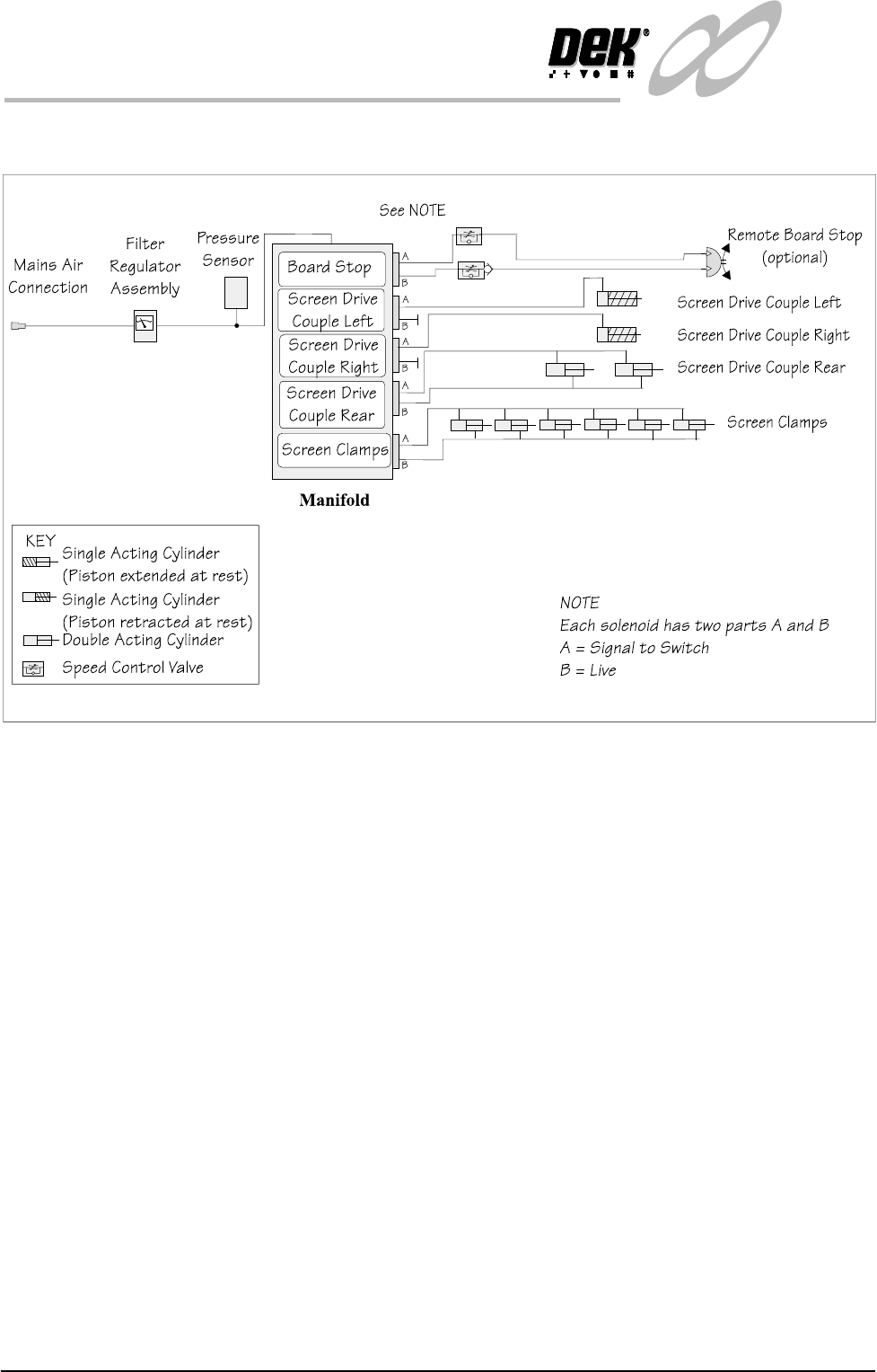
PNEUMATIC SCHEMATIC
PNEUMATIC SCHEMATIC
Figure 1-3 Pneumatic Schematic
INFINITY
TECHNICAL REFERENCE
MECHANICAL DETAIL
Chapter Issue 4 Aug 01 Infinity Dual Image Manual 1.5
MECHANICAL DETAIL
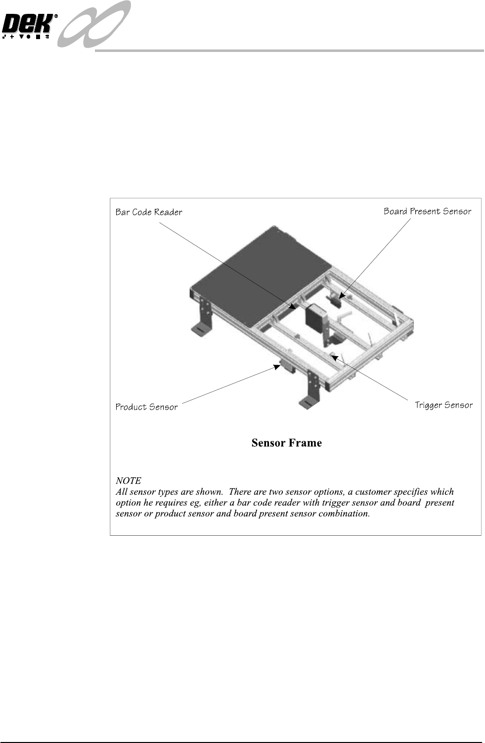
Sensor Frame A sensor frame is provided at the input conveyor, this gives support for the
respective input sensors. The frame is supplied as specified for left or right hand
input conveyor systems. If the process is altered e.g., the printing machine is
repositioned and the input conveyor is changed-over, then the sensor positions
need to be ‘mirrored’ on the frame. The product to be printed may vary in size
from one print run to the next, the frame can be quickly reconfigured to
accommodate the different board widths.
To adjust the sensor frame see Adjustments and Settings later in this chapter.
Figure 1-4 The Sensor Frame for the Left Hand Conveyor Configuration
1.6 Infinity Dual Image Manual Chapter Issue 4 Aug 01
INFINITY
TECHNICAL REFERENCE
MECHANICAL DETAIL
Screens The screens used in the machine can be single image or dual image. When dual
image mode is used, screens with runner adaptors are used (see also ‘Adapting
a 29 inch screen’).
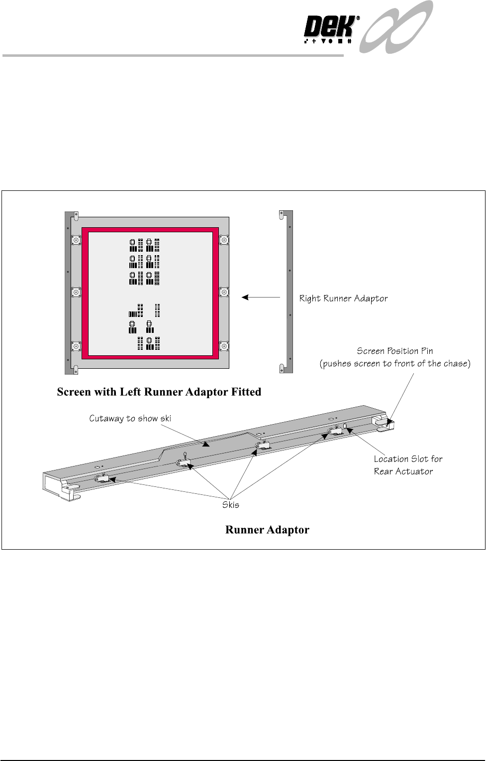
Runner Adaptor The runner adaptor set comprises two runners that are fitted to both sides of the
screen. The standard screen used for printing has a printable image area of
508mm x 508mm (20 x 20 inches), as the screen needs to shuttle front to back
in a dual image print operation the adaptors are fitted and the printable area is
reduced
Figure 1-5 Runner Adaptor