Infinity DI.pdf - 第15页
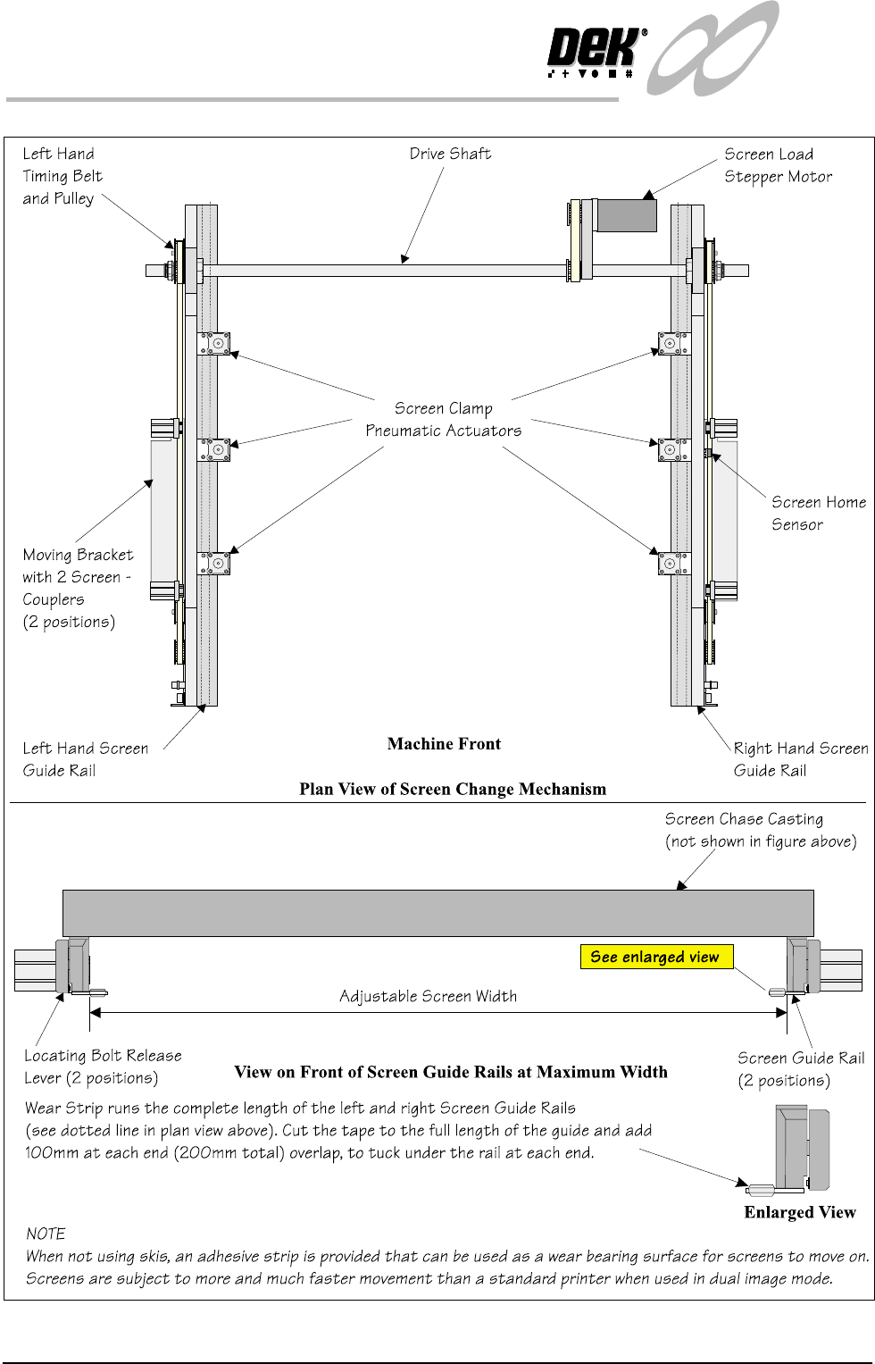
1.10 Infinity Dual Imag e Manual Chapter Issue 4 Aug 01 INFINITY TECHNIC AL RE FERENCE MECHANICAL DETAIL Figure 1-7 Screen Change Ov erview

INFINITY
TECHNICAL REFERENCE
MECHANICAL DETAIL
Chapter Issue 4 Aug 01 Infinity Dual Image Manual 1.9
Screen Change
Module
The screen change module is the mechanism which automatically loads and
unloads the screen into and out of the chase of the machine. During the screen
load sequence the module also registers a screen in the correct position for
printing.
In the dual image mode of operation, the screen load mechanism is used to
shuttle the screen on its skis to the correct position for printing.
Elements The major elements of the screen change module are:
• Screen Load stepper Motor
• Screen Clamp Pneumatic Actuators (6 Positions)
• Screen Coupling Pneumatic Actuators (4 Positions)
•Drive Shaft
• Screen Home Sensor
• Screen at Front, Centre and Rear Sensors
• Left Hand Coupling Sensor
• Right Hand coupling Sensor
• Screen in Transit ‘Front’ Sensor
• Screen in Transit ‘Rear’ Sensor
Operation Screen loading and unloading is carried out by a left and right rail system
consisting of two pneumatic screen couplers mounted on a moveable angled
bracket.
Positioning of the pneumatic screen couplers is controlled by belt and pulley
systems driven by a common stepper motor (screen move).
The left and right timing belt and pulley systems move both angled brackets and
pneumatic screen coupler actuators. The pulleys are connected to a common
drive shaft that is directly driven by the stepper motor.
Two screen transit sensors are fitted to the machine to sense the screen presence
during load and unload operations.
Image positions and screen length variations are compensated for by varying the
registered position of the frame inside the chase.
In single image mode, various screen frame sizes can be fitted to the machine by
manually adjusting the distance between the screen change rails. Details of how
to adjust the screen rail width are given in the Technical Reference Manual -
Screen Change Module, Mechanical Detail, Screen Rail Adjustment. In dual
image mode the screen and runner adaptors are used, the screen change rail
width is fixed at 652mm, hole position #4 for both rails. Where a large screen is
used, 29 inch, the rails are set to their outermost setting position #1.
1.10 Infinity Dual Image Manual Chapter Issue 4 Aug 01
INFINITY
TECHNICAL REFERENCE
MECHANICAL DETAIL
Figure 1-7 Screen Change Overview

INFINITY
TECHNICAL REFERENCE
DRIVES AND SENSORS
Chapter Issue 4 Aug 01 Infinity Dual Image Manual 1.11
DRIVES AND SENSORS
Drives
Sensors
Name Type Control Card Functional Description
Screen Load Stepper 13M1 Stepper Stepper Drive
X6 Channel 2
Moves the screen load actuators (2 on
each screen rail) via a drive shaft and
two pulley system
Name
Type
Control Card Functional Description
Bar Code Reader
(Optional)
Laser Scanner and
(Trigger) diffuse
opto sensor
X7
4 Channel RS232
Trigger sensor detects product and
switches the reader on. Laser scanner
reads the bar code label to identify the
product being printed.
Product Sensor Diffuse Opto MultiMove (IN8) Alternative to the bar code reader
option. Determines which product is
on the input conveyor.
Board Present Diffuse Opto MultiMove (IN9) Confirms the presence of a board on
the input conveyor.
Screen at Front Long throw opto
through beam
MultiMove X11
(IN6)
Senses when the screen is clear of the
front of the chase. Used by the soft-
ware to determine whether a stencil
load or unload is viable.
Screen at Rear Long throw opto
through beam
MultiMove X11
(IN5)
Senses when the screen is clear of the
rear of the chase. Used by the soft-
ware to determine whether a stencil
load or unload is viable.
Screen at Centre Long throw opto
through beam
MultiMove X11
(IN4)
Senses when the screen is clear of the
centre of the chase. Used by the soft-
ware to determine whether a stencil
load or unload is viable.
Screen in Transit Front Diffuse opto with
background sup-
pression
MultiMove X11
(IN7)
Senses the stencil position during a
stencil unload. Prevents the stencil
from hitting the machine cover.
Screen in Transit Rear Diffuse Opto MultiMove X11
(IN1)
Senses the stencil position during a
stencil unload. Prevents the stencil
from hitting the machine cover
L/H Coupling Rear
Extended
Reed Switch MultiMove X11
(IN3)
Detects when the left hand screen
coupling is fully extended.
R/H Coupling Rear
Extended
Reed Switch MultiMove X11
(IN3)
Detects when the right hand screen
coupling is fully extended.