Infinity DI.pdf - 第14页
INFINITY TECHNI CAL REFEREN CE MECH ANICA L DETAIL Chapter Issu e 4 Aug 01 Infinity Dual Imag e Manual 1.9 Scr een Change Module The screen change module is the mecha nism which automatically loads and unloads the screen…

1.8 Infinity Dual Image Manual Chapter Issue 4 Aug 01
INFINITY
TECHNICAL REFERENCE
MECHANICAL DETAIL
Customised Screens NOTE
Customers that use non standard stencils or wish to adapt a stencil should
contact DEK Customer support for details regarding the correct dimensions.

INFINITY
TECHNICAL REFERENCE
MECHANICAL DETAIL
Chapter Issue 4 Aug 01 Infinity Dual Image Manual 1.9
Screen Change
Module
The screen change module is the mechanism which automatically loads and
unloads the screen into and out of the chase of the machine. During the screen
load sequence the module also registers a screen in the correct position for
printing.
In the dual image mode of operation, the screen load mechanism is used to
shuttle the screen on its skis to the correct position for printing.
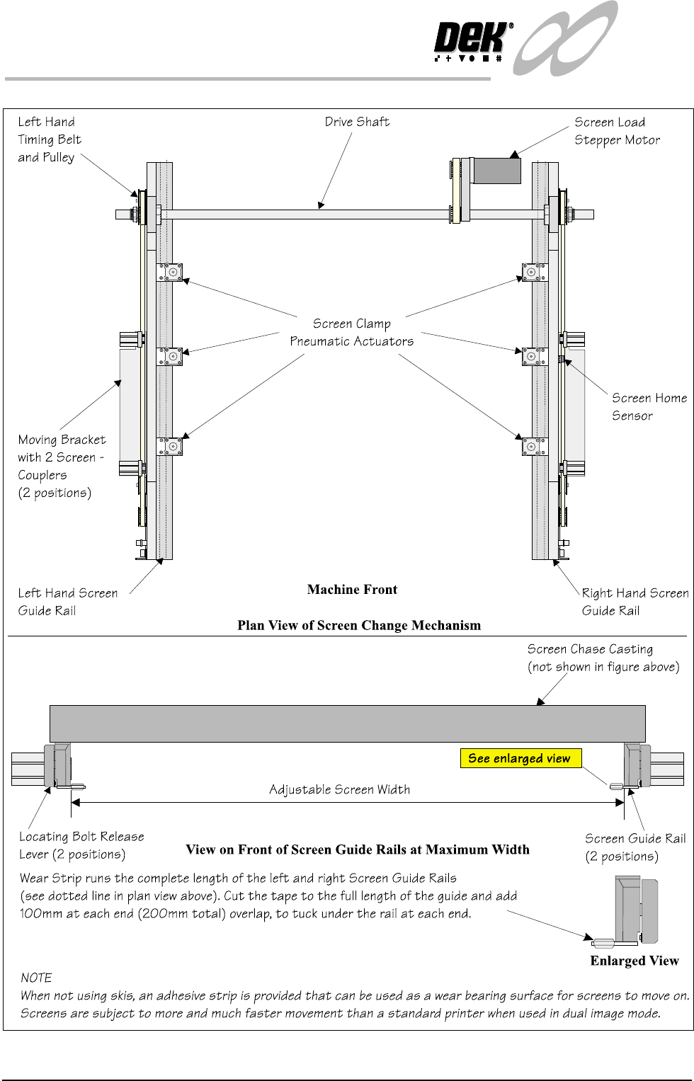
Elements The major elements of the screen change module are:
• Screen Load stepper Motor
• Screen Clamp Pneumatic Actuators (6 Positions)
• Screen Coupling Pneumatic Actuators (4 Positions)
•Drive Shaft
• Screen Home Sensor
• Screen at Front, Centre and Rear Sensors
• Left Hand Coupling Sensor
• Right Hand coupling Sensor
• Screen in Transit ‘Front’ Sensor
• Screen in Transit ‘Rear’ Sensor
Operation Screen loading and unloading is carried out by a left and right rail system
consisting of two pneumatic screen couplers mounted on a moveable angled
bracket.
Positioning of the pneumatic screen couplers is controlled by belt and pulley
systems driven by a common stepper motor (screen move).
The left and right timing belt and pulley systems move both angled brackets and
pneumatic screen coupler actuators. The pulleys are connected to a common
drive shaft that is directly driven by the stepper motor.
Two screen transit sensors are fitted to the machine to sense the screen presence
during load and unload operations.
Image positions and screen length variations are compensated for by varying the
registered position of the frame inside the chase.
In single image mode, various screen frame sizes can be fitted to the machine by
manually adjusting the distance between the screen change rails. Details of how
to adjust the screen rail width are given in the Technical Reference Manual -
Screen Change Module, Mechanical Detail, Screen Rail Adjustment. In dual
image mode the screen and runner adaptors are used, the screen change rail
width is fixed at 652mm, hole position #4 for both rails. Where a large screen is
used, 29 inch, the rails are set to their outermost setting position #1.
1.10 Infinity Dual Image Manual Chapter Issue 4 Aug 01
INFINITY
TECHNICAL REFERENCE
MECHANICAL DETAIL
Figure 1-7 Screen Change Overview