Infinity DI.pdf - 第19页
1.14 Infinity Dual Imag e Manual Chapter Issue 4 Aug 01 INFINITY TECHNIC AL RE FERENCE PNEUMATIC O VERVIEW PNEUMATIC OV ERVIE W Figur e 1-10 Pneumatics
INFINITY
TECHNICAL REFERENCE
DRIVES AND SENSORS
Chapter Issue 4 Aug 01 Infinity Dual Image Manual 1.13
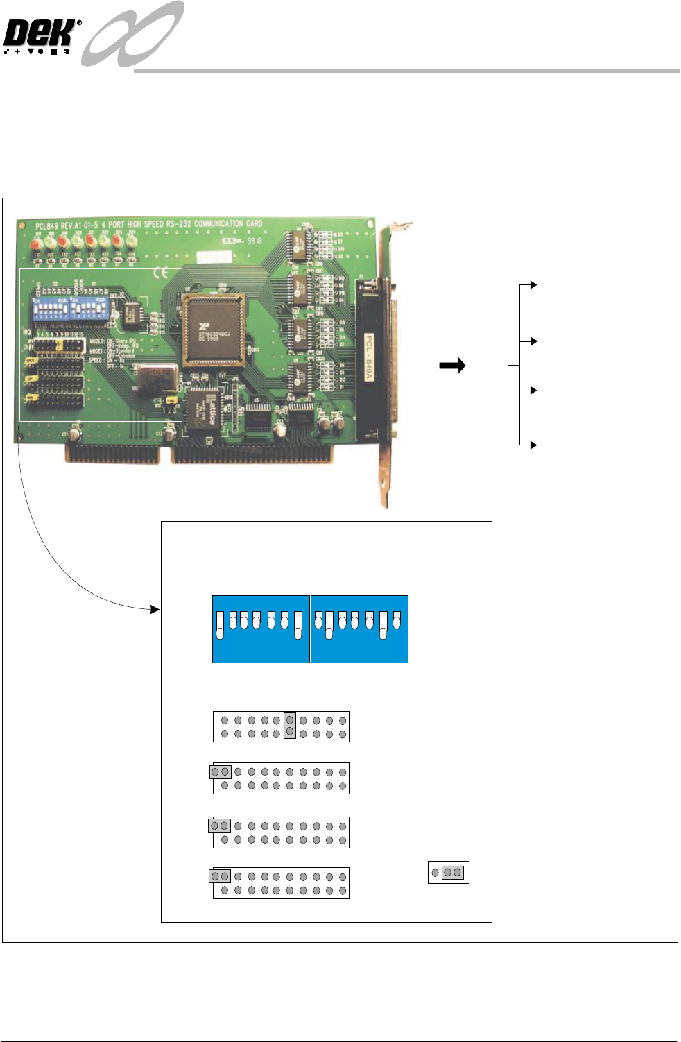
Four Channel
Comms Card
The communications card is fitted to slot X7 of the machine pc. It is used to
interface with external communications devices such as the remote bar code
reader, infra-red link and the stencil bar code reader. This card uses a shared
interrupt (IRQ) level for the available options. The correct DIP switch and
jumper link settings are shown below.
Figure 1-9 4 Channel RS232 Comms Card Set Up
3SK27 3PL27
P1 - 3PL19 - Stencil
Barcode Reader - COM5
P2 - 3PL20 - Remote
Barcode Reader -COM6
P3 - 3PL20 -
Spare -COM7
P4 - 3PL21 -
Spare -COM8
12
3
4
56
7
ON
SPEED
A3
A4
A5
A6
A7
A8
S2
12
3
4
56
7
ON
MODE0
MODE1
A4
A5
A6
A7
A8
S1
3 4 5 6 7 9 10 11 12 15
JP1
CH#1
3 4 5 6 7 9 10 11 12 15
JP2
CH#2
3 4 5 6 7 9 10 11 12 15
JP3
CH#3
3 4 5 6 7 9 10 11 12 15
JP4
CH#4
IRQ
BASE ADDRESS
VECTOR ADDRESS
JP15
123
MODE0: ON-Share IRQ
OFF-Indep.IRQ
MODE1: ON-Standard
OFF-Enhance
SPEED: ON-8x
OFF-1x
1.14 Infinity Dual Image Manual Chapter Issue 4 Aug 01
INFINITY
TECHNICAL REFERENCE
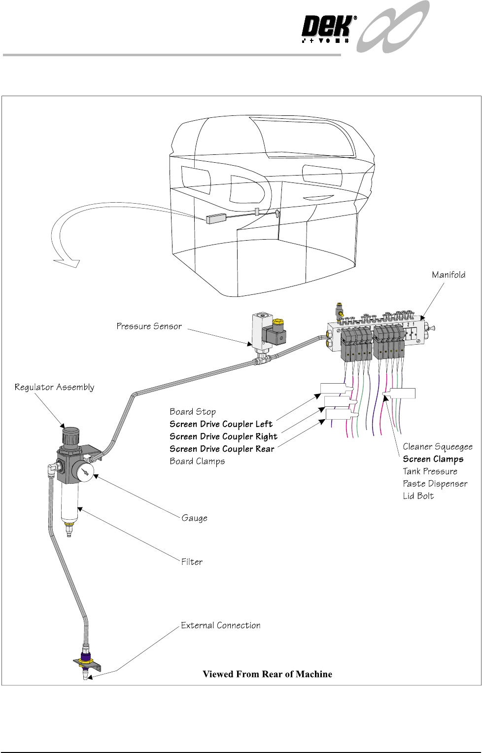
PNEUMATIC OVERVIEW
PNEUMATIC OVERVIEW
Figure 1-10 Pneumatics

INFINITY
TECHNICAL REFERENCE
SEQUENCES
Chapter Issue 4 Aug 01 Infinity Dual Image Manual 1.15
SEQUENCES
Home Sequence The screen change mechanism only carries out a homing sequence when the
machine initializes. The home sequence occurs when the system power is
applied to the machine or, when exiting the MMI Diagnostics page.
The homing sequence is as follows:
1. The screen load motor drives the mechanism toward the front of the machine.
2. The screen load motor stops when the home sensor detects the vane.
3. The screen load motor reverses direction and drives the mechanism toward
the rear of the machine.
4. The screen load motor stops the instant the sensor clears the home vane. This
is the home position.
5. The motor drives 5000 steps (343.6mm) to the rear of the machine. This is
the zero datum position, from which all screen locations are calculated.
Screen Unload If Change Screen is selected, the software interrogates the screen at front, centre
and rear sensors. the screen automatically unloads as follows:
1. The screen clamps are de-energized.
2. The drive couplings are energized and the mechanism drives the screen
toward the front.
3. The screen stops when it is detected by the screen in transit ‘front’ sensor.
4. The operator is prompted to remove the screen.
Screen Load (Single
Image Mode)
If Change Screen is selected, the software interrogates the screen at front, centre
and rear sensors. If no screen is detected the software prompts the user to insert
a screen. Once the screen has been inserted and Change Screen selected,
automatic screen load and registration takes place. An automatic screen load
sequence also takes place if the machine is initialized with a screen in the chase.
The screen load sequence is as follows:
1. The screen drive unit drives towards the front of the machine until it reaches
home position (it does not actually home).
2. The front and rear couplings are energized and grip the screen.
3. The screen is driven into the chase until it is detected by the screen at 'rear'
sensor
4. The screen is driven forward until it clears the sensor.
5. The drive couplings are de-energized.
6. The screen drive unit drives to the rear of the machine.
7. The two rear drive couplings are energized behind the screen.
8. The screen drive unit moves forward and positions the screen
9. The front right hand drive coupling is energized, pushing the screen against
the left chase rail.
10. The screen clamps are energized. The drive couplings are de-energized.