00192377-02.pdf - 第87页
SIPLACE S-23 HM 2 Retrofitting Instruct. S-23 HM to SW V 502.xx incl. RV6-DLM 1 Head (Option) 07/01 Issue 2.8 Sequence: Modifying H ardware 87 2.8.5 Att aching Designation and Overview Labels 2.8.5.1 Required: Set of lab…
2 Retrofitting Instruct. S-23 HM to SW V 502.xx incl. RV6-DLM1 Head (Option) SIPLACE S-23 HM
2.8 Sequence: Modifying Hardware 07/01 Issue
86
2
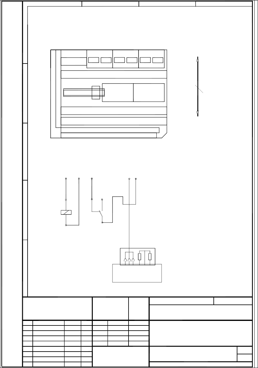
Fig. 2.8.8 Circuit Diagram: Retrofit Kit for Compressed Air Shutoff S-25 HM
11.07.00
1.
1.
1.
Tu.
00356993-010101LD4.dsf
11.07.00 Tuth
1
1
Retrofit Kit
00356993-010101LD4
Tu.
Tu.
11.07.00
11.07.00
11.07.00
11.07.00
Compressed Air Shutoff for S25HM
W
e
i
t
e
r
g
a
b
e
s
o
w
i
e
V
e
r
v
i
e
l
f
ä
l
t
i
g
u
n
g
d
i
e
s
e
r
U
n
t
e
r
l
a
g
e
,
V
e
r
w
e
r
t
u
n
g
u
n
d
M
i
t
t
e
i
l
u
n
g
i
h
r
e
s
I
n
h
a
l
t
e
s
n
i
c
h
t
g
e
s
t
a
t
t
e
t
,
s
o
w
e
i
t
n
i
c
h
t
a
u
s
d
r
ü
c
k
l
i
c
h
z
u
g
e
s
t
a
n
d
e
n
.
Z
u
w
i
d
e
r
h
a
n
d
l
u
n
g
e
n
v
e
r
p
f
l
i
c
h
t
e
n
z
u
S
c
h
a
d
e
n
e
r
s
a
t
z
.
A
l
l
e
R
e
c
h
t
e
f
ü
r
d
e
n
F
a
l
l
d
e
r
P
a
t
e
n
t
e
r
t
e
i
l
u
n
g
o
d
e
r
G
M
-
E
i
n
t
r
a
g
u
n
g
v
o
r
b
e
h
a
l
t
e
n
.
C
o
p
y
i
n
g
o
f
t
h
i
s
d
o
c
u
m
e
n
t
,
a
n
d
g
i
v
i
n
g
i
t
t
o
o
t
h
e
r
s
a
n
d
t
h
e
u
s
e
o
r
c
o
m
m
u
n
i
c
a
t
i
o
n
o
f
t
h
e
c
o
n
t
e
n
t
s
t
h
e
r
e
o
f
,
a
r
e
f
o
r
b
i
d
d
e
n
w
i
t
h
o
u
t
e
x
p
r
e
s
s
a
u
t
h
o
r
i
t
y
.
O
f
f
e
n
d
e
r
s
a
r
e
l
i
a
b
l
e
t
o
t
h
e
p
a
y
m
e
n
t
o
f
d
a
m
a
g
e
s
.
A
l
l
r
i
g
h
t
s
a
r
e
r
e
s
e
r
v
e
d
i
n
t
h
e
e
v
e
n
t
o
f
t
h
e
g
r
a
n
t
o
f
a
p
a
t
e
n
t
o
r
t
h
e
r
e
g
i
s
t
r
a
t
i
o
n
o
f
t
h
e
u
t
i
l
i
t
y
m
o
d
e
l
o
r
d
e
s
i
g
n
.
SIEMENS
Funktionsstand
Erzeugnisstand
Unterlagenstand
Maßstab
Datum Name
Zust. Mitteilung Datum Name
PLEA1
Aktiengesellschaft
Gepr.
Bearb.
Norm
(Materialnummer)
Mat.-Nr. - FS ES US S/F
Blatt
E
D
C
B
A
1234
Dateiname:
W1;W2;W3
0.50mm bl/bk
l=60cm
C
o
m
p
r
e
s
s
e
d
a
i
r
O
N
/
O
F
F
1
8
0
R
4
7
0
R
4
3
5
1
2
7
b
r
w
h
g
n
w
h
g
n
X
1
9
Joucomatic valve
0
0
3
2
2
3
5
6
-
x
x
(
0
0
3
4
8
2
6
2
-
x
x
)
b
r
11
12 14
A
2
X
2
k
d
:
M
A
2
X
2
k
d
:
7
A2
A1
W
1
A
2
X
2
k
d
:
+
A
1
X
2
k
a
:
5
R
e
l
.
1
W
2
W
3
A
2
X
2
k
d
:
M
Term. X210
Terminals X212
Terminals X211
A1
A4
X2kb
X2ka
A2
X2kd
X2kc
A3
X2kf
X2ke
R
e
l
.
1
A6
Terminal panel, LH side
Material no. 00344265-xx
Mounting location for the relay for compressed air shutoff
Single wires for internal wiring
Wiring instructions
Clip the relay onto the DIN
3 single wires W1 - W3
During that process,
disconnect the brown
wire of the cable
Jucomatic valve from A2+
and connect it to terminal 11 on the relay.
are used for the wiring.
rail next to assembly A6.
2
SIPLACE S-23 HM 2 Retrofitting Instruct. S-23 HM to SW V 502.xx incl. RV6-DLM1 Head (Option)
07/01 Issue 2.8 Sequence: Modifying Hardware
87
2.8.5 Attaching Designation and Overview Labels
2.8.5.1 Required: Set of labels for feeder locations and gantries: Item no. 00353125-01
– Not mandatory but do greatly enhance the overview, especially if an MTC is being installed.
Å Attach the labels as indicated in the package leaflet in the labelling set.
2.8.5.2 Required: Overview sticker for the folding doors on the machine frame
– Servo unit: Label with Item no. 00349181-01
New servo boards with 2 potentiometers (previously 3)
(Label changed to reflect current status = not dependent on upgrade)
– Control unit: Label with Item no. 00356629-01,
with additional backplane + TSP 210 + 3 x KSP219
Å Attach the labels on the relevant folding doors of the machine frame.
If no labels are available, provisional attach a piece of electrician’s tape and label it appropri-
ately.
2 Retrofitting Instruct. S-23 HM to SW V 502.xx incl. RV6-DLM1 Head (Option) SIPLACE S-23 HM
2.8 Sequence: Modifying Hardware 07/01 Issue
88
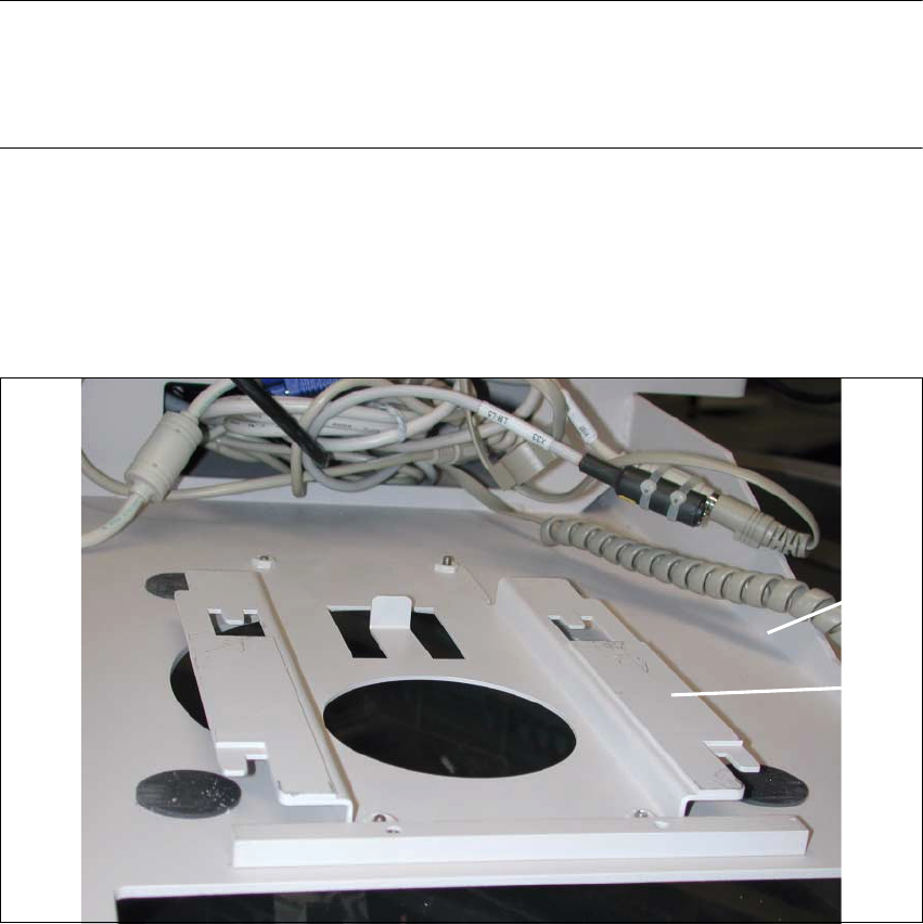
2.8.6 Up to Serial No. 350 incl.: Replace 14" monitor by 15" e156 monitor
NOTE:
The new 15" monitor incl. monitor carrier must be installed if there is still a 14" monitor.
To do so first install the adapter e156 at the PC carrier 3, fuctional status 01 and/or 02 (see also
explanation in Section 2.2). 2
Å Disconnect all connections from the back of the monitor.
Å Disconnect the keyboard, if necessary disconnect the component barcode scanner and re-
move the keyboard from the carrier.
Å Carefully lift the 14" monitor off the carrier (see Fig. 2.8.11).
Fig. 2.8.9 View of the Top of the PC Carrier 3: Adapter e156
Key:
1. PC carrier 3 (status 01 or 02)
2. Adapter e156
Å Place the adapter e156 (Item no. see Section 2.5.5) from above over the large round aperture
in the PC carrier 3 (status 01 or 02), as shown above.
Å Secure the e156 adapter to the PC carrier from the bottom of the PC carrier (see Fig. 2.8.10):
4 washers and 4 socket hex head cap screws M4 (included in Item no. 00357744S01).
2
1