EUKYX-199-2100_G5S2_Instruction_Vol2_E.pdf - 第123页
EUKYX 2-10 199-2100 2.7 Composition of Placement Data 2.7 Composition of Placement Data The set parameters are used to pla ce the components ( IDs in the pla cement feeder location da ta) on the points with the specified…
EUKYX
2-9199-2100
2.5 Composition of Placement Nozzle Data
2.5 Composition of Placement Nozzle Data
The set parameters are used to place the nozzles onto the specified positions on the head (Place
Head/Noz No.).
Refer to “3.5 PL Head/Nozzle” in this chapter for the details of each item according to the
reference Nos. (Ref. Nos.).
E01 Nozzle Place Data
Items Ref. No.
Nozzle Place (E01)
Nozzle Stk 1 (E02)
Nozzle Stk 2 (E02)
2.6 Composition of Placement Feeder Location Data
The set parameters are used to determine which feeder slot Nos. (Fdr No.) various types of
components should be allocated to.
Component IDs (types of components to be allocated) must be specified for each individual feeder
bases.
Refer to 3.6 CMPNT PL in this chapter for the details of each item according to the reference
Nos. (Ref. Nos.).
F01 CMPNT PL Data
Items Ref. No.
Fdr No. (F01_01)
Component ID (F01_02)
C (Control Command) (F01_03)
Comment (F01_04)
Feeder Fixed (F01_05)
Feeder Alternate (F01_06)
Fdr No. (F01_07)
Component Library Comment (F01_08)
Dir [deg], Carrier Data Type, Width [mm] (F01_09)
Fd. Pitch [mm] (F01_10)
Used Parts (F01_11)
Nozzle Type (F01_12)
Reference
Reference
EUKYX
2-10199-2100
2.7 Composition of Placement Data
2.7 Composition of Placement Data
The set parameters are used to place the components (IDs in the placement feeder location data) on
the points with the specified coordinates in the designated direction.
One step is allocated for each component to be placed.
Refer to 3.7 Placement in this chapter for the details of each item.
G01 Placement Data
Items Ref. No.
Un (G01_01)
Offset Data (G02)
Offset (G02)
Unit Control (G02_01)
Offset
X [mm], Y [mm], Z [ ° ], H [mm]
(G02_02)
Unit PCB Fiducial (G02_03)
Recog Coord
X1, Y1, X2, Y2
(G02_04)
Fiducial Mark
FM1, FM2
(G02_05)
P-Data (G03)
PNo. (G03_01)
X [mm], Y[mm] (G03_02)
Z [ ° ] (G03_03)
H [mm] (G03_04)
Component ID (G03_05)
Fdr. No. (G03_06)
Symbol (G03_07)
C (G03_08)
Comment (G03_09)
O-Data (G04)
Ono. (G04_01)
X [mm], Y[mm] (G04_02)
Z [ ° ] (G04_03)
H [mm] (G04_04)
C (G04_05)
Comment (G04_06)
B-X, B-Y (G04_07)
Reference
EUKYX
2-11199-2100
3.1 Common SET
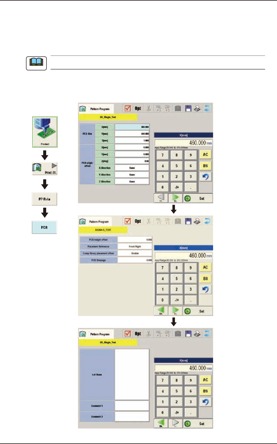
3. Explanation of Pattern Program
In this instruction manual, the placement coordinate reference is based on “Front Right”.
3.1 Common SET
This data is used in the dual transfer operation (option).
3.2 PCB
(B01) PCB Data
Graphic
Development
F2B3
Note