ED-7306_E.pdf - 第5页
JEITA ED-7306 - 3 - NOTE : The edge margin L indicates the exempt ar ea from measurement to avoid measurem ent noise depending on the instrument capability. Recom mended edge margin L=0. 2 mm. Fig. 3 Measuring zone of FL…
JEITA ED-7306
- 2 -
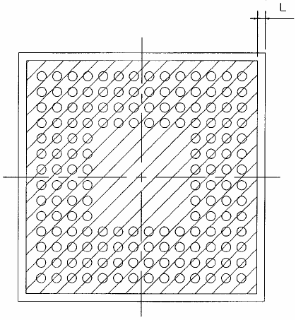
b) For the packages whose standoff height is 0.1 mm or less, such as FLGA, the measuring area is the
substrate surface except certain edge margin (See Fig. 3, dimension L). The width of this margin L
depends on the capability of each measuring instrument (0.2 mm recommended).
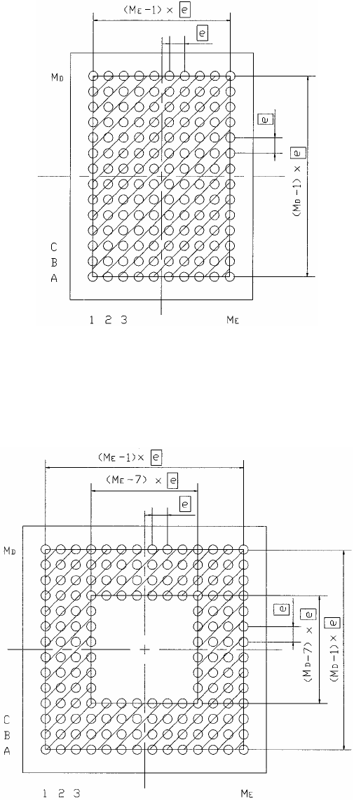
NOTE: The hatched area indicates the measuring zone.
Fig. 1 Measuring zone of BGA and FBGA in full grid layout
Fig. 2 Measuring zone of BGA and FBGA perimeter layout with 4 rows and 4 columns
JEITA ED-7306
- 3 -
NOTE: The edge margin L indicates the exempt area from measurement to avoid measurement
noise depending on the instrument capability. Recommended edge margin L=0.2 mm.
Fig. 3 Measuring zone of FLGA perimeter layout with 4 rows and 4 columns
3.2 Convex warpage
Arched top surface (not interconnect side) of package being mounted on PWB. The sign of the convex
warpage is defined as plus.
3.3 Concave warpage
Inward-curving top surface (not interconnect side) of package being mounted on PWB. The sign of the
concave warpage is defined as minus.
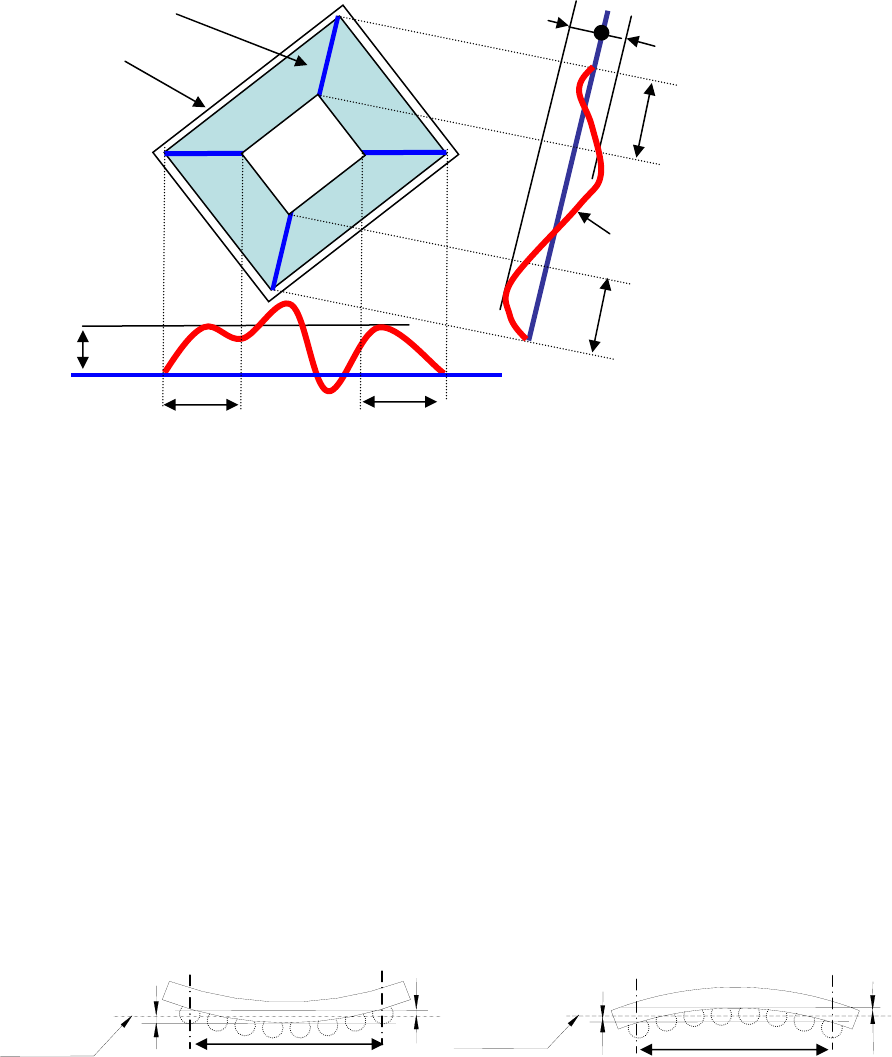
3.4 Package warpage sign
Plus or minus sign of package warpage determined by the sign of the sum of the largest positive
displacement and the largest negative displacement of the package profile on both measurement zone
diagonals. These diagonals are regarded as base lines connecting the outermost opposite corners of the
measuring zone. The sign of the package warpage is defined as the sign of:
(AB
MAX
+AB
MIN
+CD
MAX
+CD
MIN
).
AB
MAX
is the largest positive displacement and AB
MIN
is the largest negative displacement of the package
profile on the diagonal AB; (The sign of AB
MAX
is plus and AB
MIN
is zero in Fig. 4.)
CD
MAX
is the largest positive displacement and CD
MIN
is the largest negative displacement of the package
profile on the diagonal CD; (The sign of CD
MAX
is plus and that of CD
MIN
is minus in Fig. 4.)
The concave or convex impression of the package warpage can differ from the above defined sign, in
critical case.
JEITA ED-7306
- 4 -
Fig. 4 Calculation of the sign of package warpage
3.5 Package warpage
The difference of the largest positive and the largest negative displacements of the package warpage in the
measuring zone with respect to the reference plane, preceded by package warpage sign. This reference
plane is derived using the least square method with the measuring zone data. For example, the absolute
value of the package warpage ⏐C⏐ is obtained by the sum of the absolute value of the largest positive
displacement ⏐A⏐ and that of the largest negative displacement ⏐B⏐. This is in respect to the reference
plane which is derived by using the least square method, as shown in Fig. 5. Package warpage sign
precedes ⏐C⏐.
⏐C⏐=⏐A⏐+⏐B⏐
Fig. 5 Package warpage
AB
MAX
AB
MIN
=0
Base line
Package
A B
D
CD
MAX
CD
MIN
Depopulated
zone
Package warpage profile
Measuring zone diagonal
Measuring zone diagonal
Measuring zone diagonal
Measuring zone diagonal
C
Measuring zone
B
A
Concave
Measuring zone
A
B
Convex
Measuring zone
Reference
plane
Reference
plane