Host Computer System.pdf - 第10页
AVK3 HOST COMPUTER SYSTEM 1.1 RS-232C D77HEC-51- 010-A1 1.1- 1 1.1. RS-232C D77HEC - 51-010-A 1 1.1.1 Introduct ion Thi s m anual i s us ed when t he m achi ne is operated by a host com puter and it i s m ainly f ocused …

AVK3
HOST COMPUTER SYSTEM
1. HOST COMPUTER SYSTEM INTERFACE SPECIFICATIONS
D77HEC-51-000-A0
1-2
D77HEC-51-000-A0
1. HOST COMPUTER SYSTEM
INTERFACE SPECIFICATIONS
AVK3
HOST COMPUTER SYSTEM
1.1 RS-232C
D77HEC-51-010-A1
1.1-1
1.1. RS-232C
D77HEC-51-010-A1
1.1.1 Introduction
This manual is used when the machine is operated by a host computer and it is mainly focused on the
connecting interface. It has no relationship to the performance of the machine. Rather, it is concerned with
connection of RS-232C interface. If controlling the machine in groups, determine specification after
thoroughly reading this manual.
This manual is written for use with AVK3 (Panadac-783K).
=REMARKS=
Be aware that contents of this manual are subject to change without prior notice.
1.1.2 Standard Interface Specifications
Interface EIA standard RS-232C
Number of channels 1 channel <DTE specifications, 25-pin connector (socket) output>
Synchronizing type Asynchronous mode/Start-stop synchronous type
Communication system Duplex/(half duplex) However, protocol is handshaking system.
Transfer speed 2,400 / 4,800 / 9,600 / 19,200 bps
Start Data Parity Stop Total
Bit pattern
1 7 1 1 10
Error control system Vertical parity check <even parity>
Bit transfer order Low position first <from LSB>
1.1.3 RS-232C Interface (Hardware)
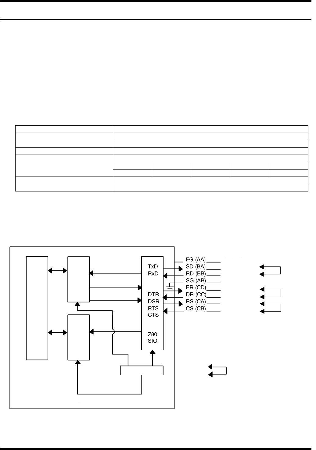
This chapter deals with the RS-232C interface circuit used in the AVK3 system.
Voltage connection is standard for the RS-232C.
186
main
CPU
Z80B
main
CPU
Z80B
main
CPU
Data line
Write control
Read control
Inter-
rupt
Oscillation circuit
Control unit
Frame ground
Transmitted data
Received data
Signal ground
Terminal ready
Data set ready
Request to send
Clear to send
=REMARKS=
Signals marked are used as a pair.
AVK3
HOST COMPUTER SYSTEM
1.1 RS-232C
D77HEC-51-010-A1
1.1-2
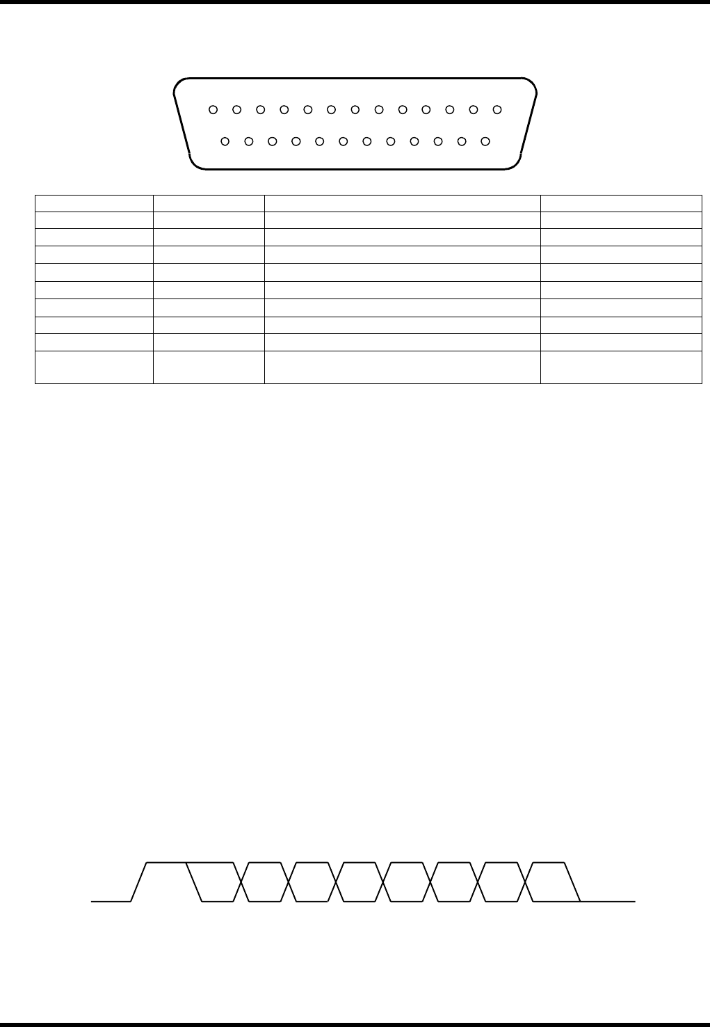
The following shows each signal connector pin array in standard RS-232C.
Connectors abide by the RS-232C standard 25-pin composition.
Pin Number Signal Symbol Signal Name Signal Direction
1 AA Frame ground (FG)
2 BA Transmitted data (SD)
AVK3 →
3 BB Received data (RD)
AVK3 ←
4 CA Request to send (RS)
AVK3 →
5 CB Clear to send (CS)
AVK3 ←
6 CC Data set ready (DR)
AVK3 ←
7 AB Signal ground (SG) AVK3 -
20 CD Terminal ready (ER)
AVK3 →
8 - 19
21 - 25
NC Not used
1.1.4 External Connection Specification for the Machine
Communication Circuit
There is only one circuit from AVK3. Since the voltage system is adopted, for medium distance or long
distance transmission (telephone circuit), it is necessary to set a modem at the output of AVK3.
The transmission distance of RS-232C, without a modem, is shorter than 15m (50 feet) as it is the
transmission circuit of the unbalanced circuit.
Actually, up to 30m can be covered, but it varies with the various conditions, so it would be preferable
to consult us if questions arise.
Communication System
The start-stop synchronous type and full duplex communication system.
However, protocol is handshaking system.
Communication Speed
The baud rate is changeable and the following settings are possible:
2400 4800 9600 19200 bps
However, standard setting is 4800 bps.
Connectors
Connected using 25-pin AM205208-1 mounted to the front panel of the P783K controller.
Transmission Unit Configuration
The transmission unit as shown in the following figure is composed of 1 start bit, 7 data bits, 1 parity bit
and 1 stop bit; namely 10 bits in total.
13 12 1110987654321
25 24 23 22 21 20 19 18 17 16 15 14
STA 0 1 2 4356P STP