Host Computer System.pdf - 第12页
AVK3 HOST COMPUTER SYSTEM 1.1 RS-232C D77HEC-51- 010-A1 1.1- 3 Control Code In t he t ransmission uni t, AS CII code wit h parit y is used. The f o ll owing i s the chart of ASCII code. b6 → 0 0 0 0 1 1 1 1 b5 → 0 0 1 …
AVK3
HOST COMPUTER SYSTEM
1.1 RS-232C
D77HEC-51-010-A1
1.1-2
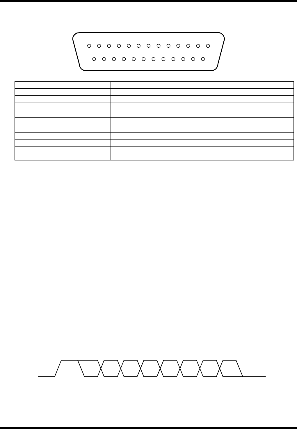
The following shows each signal connector pin array in standard RS-232C.
Connectors abide by the RS-232C standard 25-pin composition.
Pin Number Signal Symbol Signal Name Signal Direction
1 AA Frame ground (FG)
2 BA Transmitted data (SD)
AVK3 →
3 BB Received data (RD)
AVK3 ←
4 CA Request to send (RS)
AVK3 →
5 CB Clear to send (CS)
AVK3 ←
6 CC Data set ready (DR)
AVK3 ←
7 AB Signal ground (SG) AVK3 -
20 CD Terminal ready (ER)
AVK3 →
8 - 19
21 - 25
NC Not used
1.1.4 External Connection Specification for the Machine
Communication Circuit
There is only one circuit from AVK3. Since the voltage system is adopted, for medium distance or long
distance transmission (telephone circuit), it is necessary to set a modem at the output of AVK3.
The transmission distance of RS-232C, without a modem, is shorter than 15m (50 feet) as it is the
transmission circuit of the unbalanced circuit.
Actually, up to 30m can be covered, but it varies with the various conditions, so it would be preferable
to consult us if questions arise.
Communication System
The start-stop synchronous type and full duplex communication system.
However, protocol is handshaking system.
Communication Speed
The baud rate is changeable and the following settings are possible:
2400 4800 9600 19200 bps
However, standard setting is 4800 bps.
Connectors
Connected using 25-pin AM205208-1 mounted to the front panel of the P783K controller.
Transmission Unit Configuration
The transmission unit as shown in the following figure is composed of 1 start bit, 7 data bits, 1 parity bit
and 1 stop bit; namely 10 bits in total.
13 12 1110987654321
25 24 23 22 21 20 19 18 17 16 15 14
STA 0 1 2 4356P STP
AVK3
HOST COMPUTER SYSTEM
1.1 RS-232C
D77HEC-51-010-A1
1.1-3
Control Code
In the transmission unit, ASCII code with parity is used. The following is the chart of ASCII code.
b6 →
0 0 0 0 1 1 1 1
b5 →
0 0 1 1 0 0 1 1
b4 →
0 1 0 1 0 1 0 1
Hex-
adec-
imal
0 1 2 3 4 5 6 7
Bit
(7 bit)
bbbb
3210
↓↓↓↓
Hexadeci-
mal
0000 0 NUL DLE SP 0 @ P ‘ p
0001 1 SOH DC1 ! 1 A Q a q
0010 2 STX DC2 ” 2 B R b r
0011 3 ETX DC3 # 3 C S c s
0100 4 EOT DC4 $ 4 D T d t
0101 5 ENQ NAK % 5 E U e u
0110 6 ACK SYN & 6 F V f v
0111 7 BEL ETB ’ 7 G W g w
1000 8 BS CAN ( 8 H X h x
1001 9 HT EN ) 9 I Y i y
1010 A LF SUB
∗
: J Z j z
1011 B VT ESC + ; K [ k {
1100 C FF FS , < L l !
1101 D CR GS - = M ] m }
1110 E SO RS
⋅
> N ^ n ~
1111 F SI US / ? O _ o DEL
1.1.5 Basic Transmission Timing of Transmission Unit
One character basic transmission timing of AVK3 is as shown below.
ER signal (Terminal ready signal) is set by the initial process when power is turned on, and can be reset
simply by the emergency stop switch.
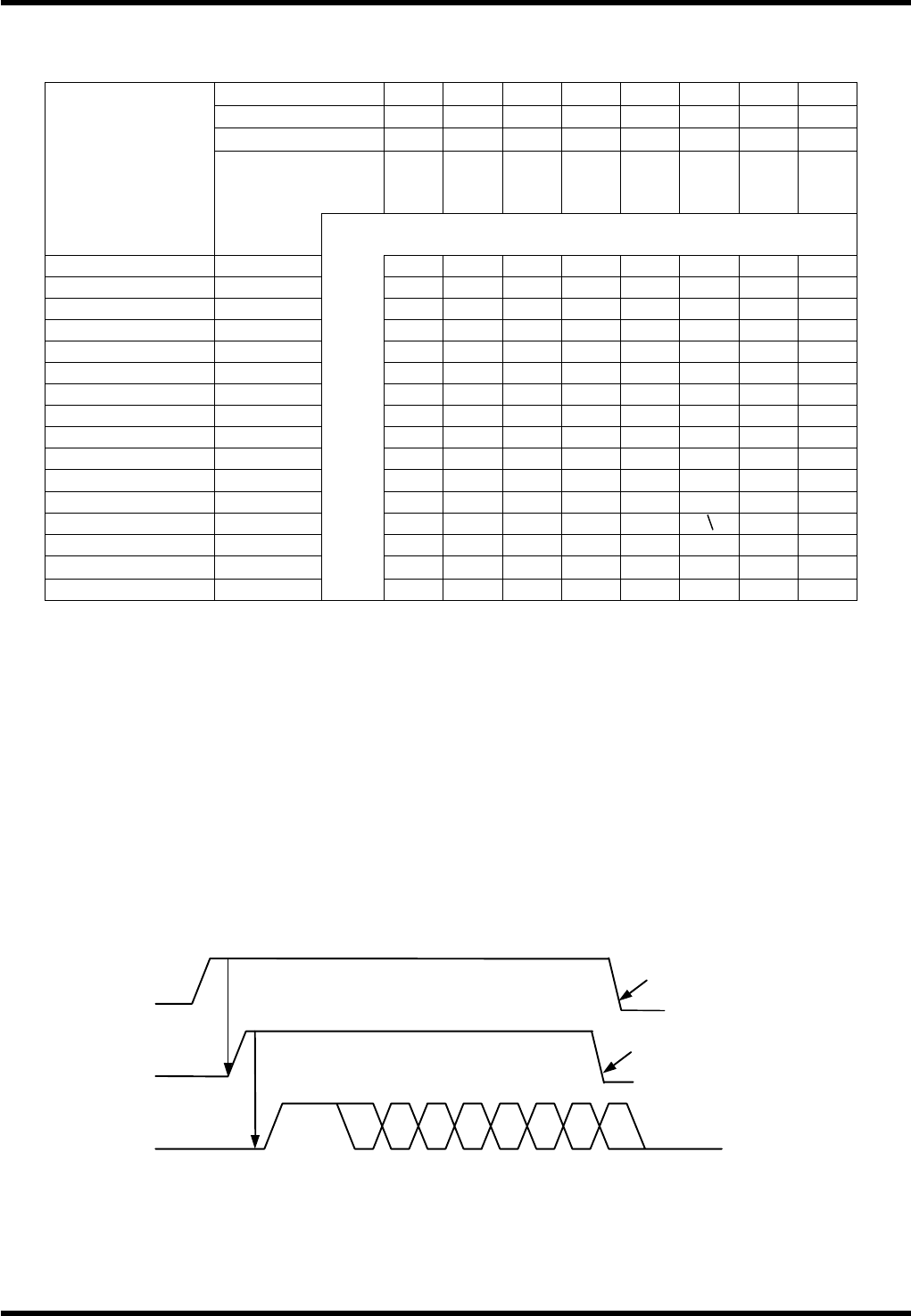
1) Character sending timing
When the request to send signal (RS) is output to the other interface side, the clear to send the signal
(CS) will come back from the other side. Then, characters are automatically sent from AVK3.
The CS signal is called “clear to send”, and if the other side is in a receiving mode, the characters are
always output, especially if the other side has a hardware buffer of a certain degree.
RS (Output)
S 0 1 3245P6S
Turns ON the request to send signal.
Clear to send signal returns.
When status TXE turns “ON”
RS output turns “OFF”.
When receiving process starts, RS
output turns “OFF”.
CS (Input)
SD (Output)

AVK3
HOST COMPUTER SYSTEM
1.1 RS-232C
D77HEC-51-010-A1
1.1-4
Since the DR (Data set ready) signal means the other interface terminal side is ready, it checks only if
“ON” at the startup process of character sending. If DR signal is “OFF”, character sending waits until it
is turned “ON”.
2) Character receiving timing
For receiving characters there are not restrictions or conditions in communications, so all characters
output by the Host computer can be read. However, the characters received when processing the
received command are neglected.
1.1.6 Changing Data Transmission Mode
Because the control of RS-232C interface varies with the type of host computer, the machine is equipped
with mode changeover switches.
1) Optional break character function
In some cases, inputting of break character may cause inconvenience. In this case, turn the
changeover SW ON and the outputting of the break character from the AVK3 becomes ineffective.
2) Optional check sum function
The data transmission format includes check sum data. Even if the results of this check sum data
accumulation are in error, it is okay with this changeover switch. Check sum data is necessary to
comply with format, so do not forget to add dummy figures.
3) R commands
If a host computer is used for only NC data transmission, there may be trouble whenever real time
information is input to the host computer. If the changeover switch is ON, all R commands from AVK3
will be blocked.
4) Momentary selection of M and T commands at the time of NC data output
When the NC data in AVK3 is output to the host computer by C1 command, normally, even if M and T
commands are the same, the respective blocks are output similarity as in T1M1. This results in
increased time for data transmission. Therefore, when M and T commands are the same, the
command part can be out and it is this changeover switch that shortens the data.
5) Optional time-out processing
Turn ON changeover switch when you do not want time out processing.
6) End code selection
Turn the changeover switch to CR when using CR code for ETX as the message end code.