00197465-01_SM_CP20-A-M_EN.pdf - 第66页
5 Settings 5.6 Transferring the head sp ecific data 5.6.2 Transferring the H ead-Specific Data (from SW701) 66 Service Manual SIPLACE C&P20, C&P20A, C&P20M
5 Settings
5.6.2 Transferring the Head-Specific Data (from SW701) 5.6 Transferring the head specific data
Service Manual SIPLACE C&P20, C&P20A, C&P20M 65
5.6.2
5.6.2 Transferring the Head-Specific Data (from SW701)
Transferring the Head-Specific Data (from SW701)
After changing the head hardware, the new head data
need to be imported from the head EPROM in the soft
-
ware.
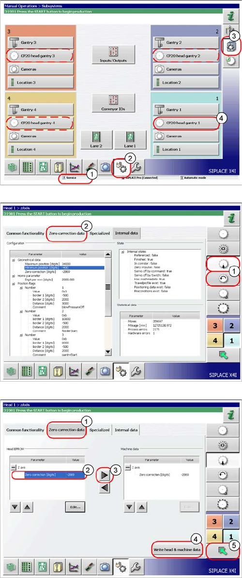
► Switch the machine on.
► Select the user level Service (customer) (1).
► Switch over to the menu Check sensors and
functions (2).
► Click on the button Check sensors and functions of
specific components (3).
► Click on the button CP20 head, gantry x for the gantry
concerned (4).
► Select the Z axis/star axis (1).
► Select Zero correction data (2).
This is where the axis data (Z and star axes) can be writ
-
ten from the head EPROM to the machine data. You can
also write the Z and star axis data from the machine data
to the head EPROM.
► In the Zero correction data (1) select the line Zero
point correction (2).
► ;Move the value out of the head EPROM and into the
machine data (3).
► Select Write head & machine data (4).
► The arrow button (5) takes you back one menu level.
5 Settings
5.6 Transferring the head specific data 5.6.2 Transferring the Head-Specific Data (from SW701)
66 Service Manual SIPLACE C&P20, C&P20A, C&P20M
6 Description of the Circuit Boards
6.1 Intermediate distributor C&P20 [03002942-xx]
Service Manual SIPLACE C&P20, C&P20A, C&P20M 67
6
6 Description of the Circuit Boards
Description of the Circuit Boards
6.1
6.1 Intermediate distributor C&P20 [03002942-xx]
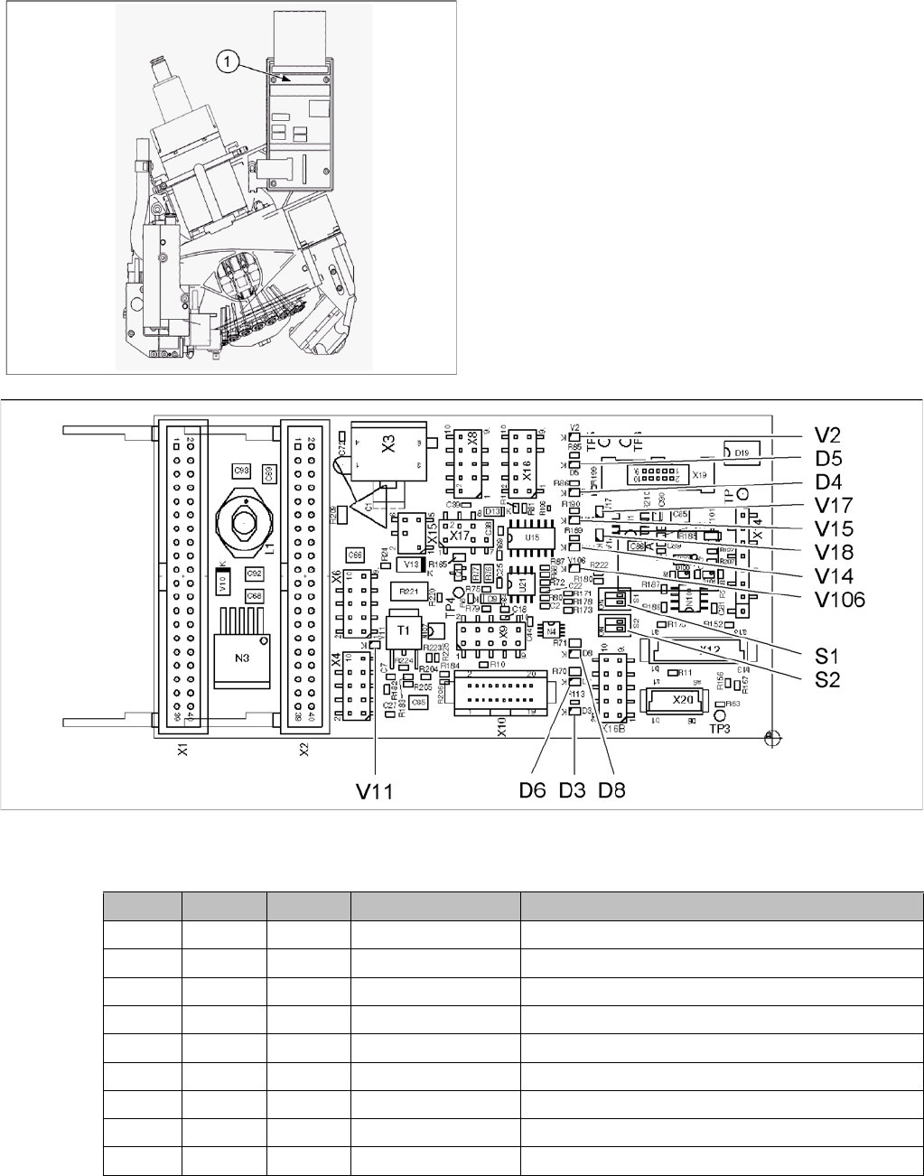
Intermediate distributor C&P20 [03002942-xx]
03002942-09
LED [03002942-09]
1. Intermediate distributor board on C&P20(A) head
LED Color Status Signal name Description
D3 GN ON 5V+ +5VDC operating voltage
D4 YE ON Z_BOTTOM Z bottom sensor activated
D5 YE ON Z_TOP Z top sensor activated
D6 GN ON 15V+ +15VDC operating voltage
D8 GN ON 15V- -5VDC operating voltage
V2 GN ON V4_OUT Z valve activated
V11 YE ON EN_FESTO Return cylinder activated
V14 GN ON 24V+_VHS +24VDC operating voltage, VHS
V15 GN ON 24V+_DP +24VDC operating voltage, DP