00197465-01_SM_CP20-A-M_EN.pdf - 第71页
6 Description of the Circuit Boards 6.2 VLT23 [03003002-xx] Service Manual SIPLACE C&P20, C&P20A, C&P20M 71 6.2 6 . 2 V L T 2 3 [ 0 3 0 0 3 0 0 2 - x x ] VLT23 [03003002-xx] 03003002-04 LED [03003002-04] 6.3 …

6 Description of the Circuit Boards
6.1 Intermediate distributor C&P20 [03002942-xx]
70 Service Manual SIPLACE C&P20, C&P20A, C&P20M
Test points
Test connector X14
V14 +24V Present Not present
V15 +24 V_DP Switched on Switched off
V16/17 Voltage GND
No. Function
TP1 GND
TP3 Voltage pressure signal, internal pressure control valve
TP4 Output voltage I/U converter Z bottom
TP5 Z bottom
TP6 Z top/Z bottom - reset
Pin Signal
1CAN_RX
2GND
3+5V
4+15V
5-15V
6 X2_11
724V_DP
8 Z top/Z bottom - reset
No. Function On OFF
6 Description of the Circuit Boards
6.2 VLT23 [03003002-xx]
Service Manual SIPLACE C&P20, C&P20A, C&P20M 71
6.2
6.2 VLT23 [03003002-xx]
VLT23 [03003002-xx]
03003002-04
LED [03003002-04]
6.3
6.3 ED distributor C&P20 [03003082-xx]
ED distributor C&P20 [03003082-xx]
03003082-04
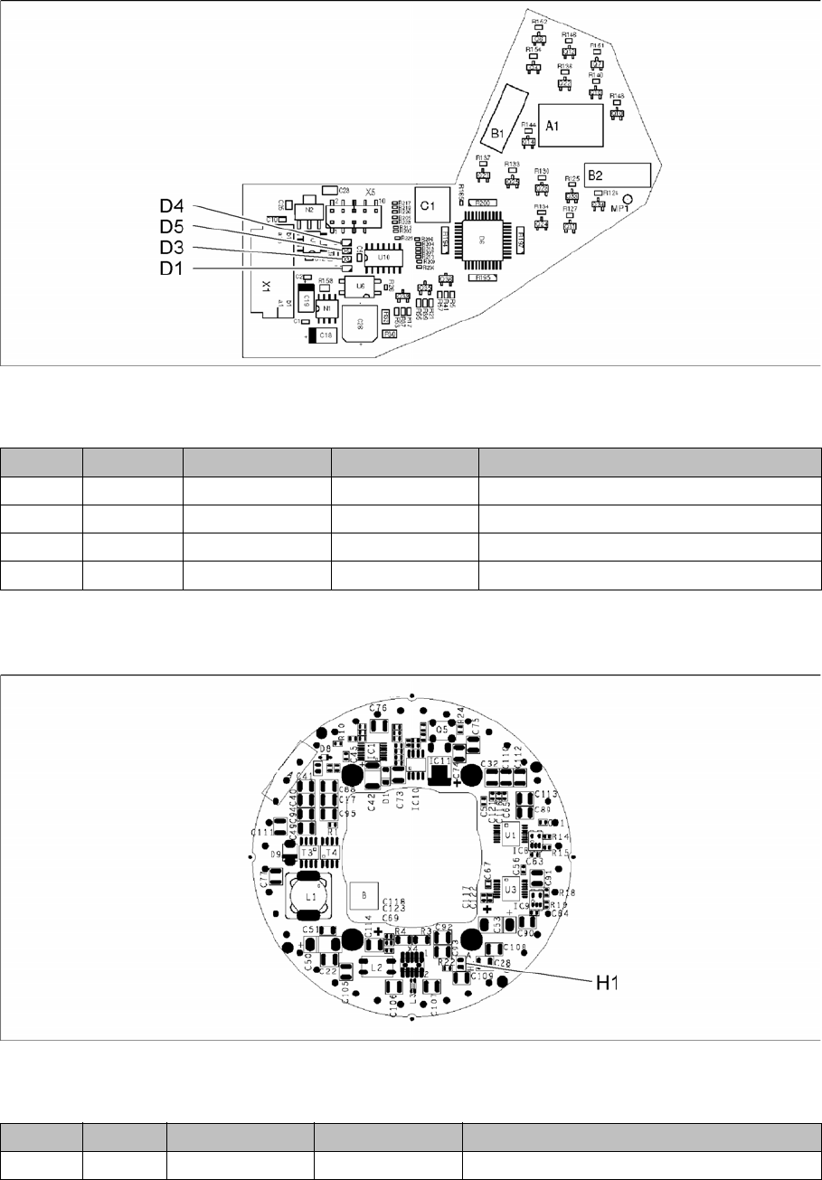
LED [03003082-04]
LED Color Status Signal name Description
D1 GN ON 40 V_IN +40VDC operating voltage
D3 GN ON 15V+ +15VDC operating voltage
D4 GN ON 15V- -15VDC operating voltage
D5 GN ON 5V+ +5VDC operating voltage
LED Color Status Signal name Description
H1 GN ON P3V3 +3.3VDC operating voltage
6 Description of the Circuit Boards
6.3 ED distributor C&P20 [03003082-xx]
72 Service Manual SIPLACE C&P20, C&P20A, C&P20M