ap-az9502-high-frequency-ac-ionizing-air-nozzle-new.pdf - 第5页
Pr oduct Appear ance Pr oduct Dimension Unit:mm P ower Indicator Light - Green High V oltage Operation Abnormal Indicator Light - Red Discharge Needle High V oltage Bo x RJ45 P ower Port Regula ting Valve Air Nozzle Disc…
Model
AP-AZ9502-485 AP-AZ9502-IO
Input Voltage
DC24V ±1V
Electrode Voltage
High-Frequency AC:V
pp
=9000V
Input Current
< 83mA
Power
< 2W
Working Distance
150-300mm
Air Pressure
0.1-0.5MPa
Air Inlet
Ф6mm
Discharge Time
< 1.0s(150mm right ahead of the nozzle)
Ion Balance
|± 15V|(150mm right ahead of the nozzle, Air pressure 0.3MPa)
Status Indicator
Power Indicator Geen Power Normal
Off
Power Abnormal
Operation Indi-
cator
Geen Operating Normally
Nozzle Not Running /
Operating
Alarm Indicator Red
High-Voltage Fault (Oper-
ation light off)
High Voltage Normal
Operating
Temperature
0-40℃
Operating
Humidity
30—70%RH (No Condensation)
Ozone Level
< 0.03ppm
Power Adapter
MODEL:T6-2400500
INPUT:AC100V-240V 50Hz-60Hz 0.3A
OUTPUT:DC24V 0.5A
Dimensions
(L*W*H)
Nozzle (with mounting bracket) 103*25.5*61.25mm
Power Adapter 71*43*30mm
RJ45 Power Cable Length 2.5m(Default)
Power Adapter
Nozzle (with mounting bracket) 120.1g
Power Adapter: 101.3g
Gross Weight
470.9g
■
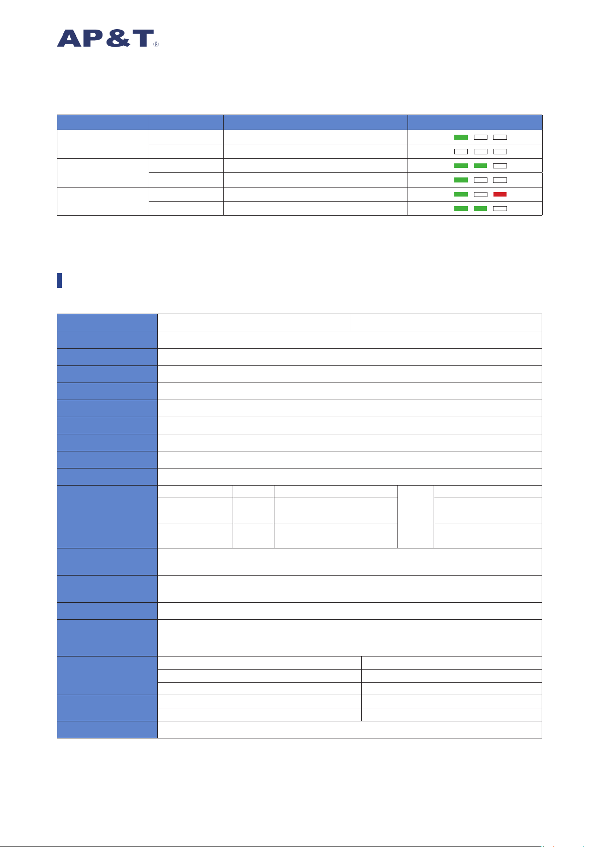
Visual status indicator function:
Indicator Type Light Color Device Status Indicator Description
Power Indicator
Green Power supply normal
Off Power supply abnormal
Operation
Indicator
Green Operating / Working normally
Off Nozzle not running / operating
Alarm Indicator
Red High-voltage fault (operation light off)
Off High voltage normal
Product Parameter
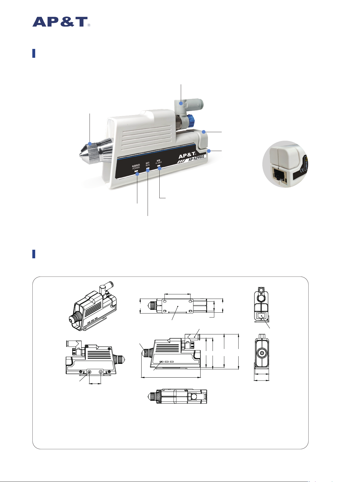
Product Appearance
Product Dimension
Unit:mm
Power Indicator Light -
Green
High Voltage Operation
Abnormal Indicator Light - Red
Discharge Needle High Voltage Box
RJ45 Power Port
Regulating Valve
Air Nozzle Discharge Head / Nozzle
Operation Indicator Light -
Green
25.5
25.5
103
51 54
58.25 61.25
45
17
24
24
20
①
⑥
③
④
⑤
②
① Air Nozzle Discharge Head / Nozzle
② RJ45 Power Port
③ Working Status Indicator Light
④ ∅ 6Intake Throttle Valve
⑤ Mounting Bracket
⑥ M3 Fixing Hole
0.1 0.2 0.3 0.4 0.5 0.6
10
8
6
4
2
0
2
4
6
8
10
0.1 0.2 0.3 0.4 0.5 0.6
10
8
6
4
2
0
2
4
6
8
10
0.1 0.2 0.3 0.4 0.5 0.6
0.2
0.3
0.4
0.5
0.6
0.7
0.8
0.9
1
1.1
1.2
1.3
1.4
1.5
1.6
1.7
1.8
1.9
2
2.1
0.1 0.2 0.3 0.4 0.5 0.6
0.2
0.3
0.4
0.5
0.6
0.7
0.8
0.9
1
1.1
1.2
1.3
1.4
1.5
1.6
1.7
1.8
1.9
2
2.1
Static Decay Time(s)
Ion Balance(V
)
Static Decay Time(s)
Ion Balance(V
)
Air Pressure(MPa) Air Pressure(MPa)
∅
8 Intake Throttle Valve -t+:150mm Test Distance
∅
8 Intake Throttle Valve-t-:150mm Test Distance
∅
8 Intake Throttle Valve -t+:300mm Test Distance
∅
8 Intake Throttle Valve -t-:300mm Test Distance
∅
8 Intake Throttle Valve -Bal:150mm Test Distance
∅
8 Intake Throttle Valve -Bal:300mm Test Distance
Gas Flow Rate(L/min)
∅
6 Intake Throttle Valve -t+:150mm Test Distance
∅
6 Intake Throttle Valve-t-:150mm Test Distance
∅
6 Intake Throttle Valve -t+:300mm Test Distance
∅
6 Intake Throttle Valve -t-:300mm Test Distance
∅
6 Intake Throttle Valve -Bal:150mm Test Distance
∅
6 Intake Throttle Valve -Bal:300mm Test Distance
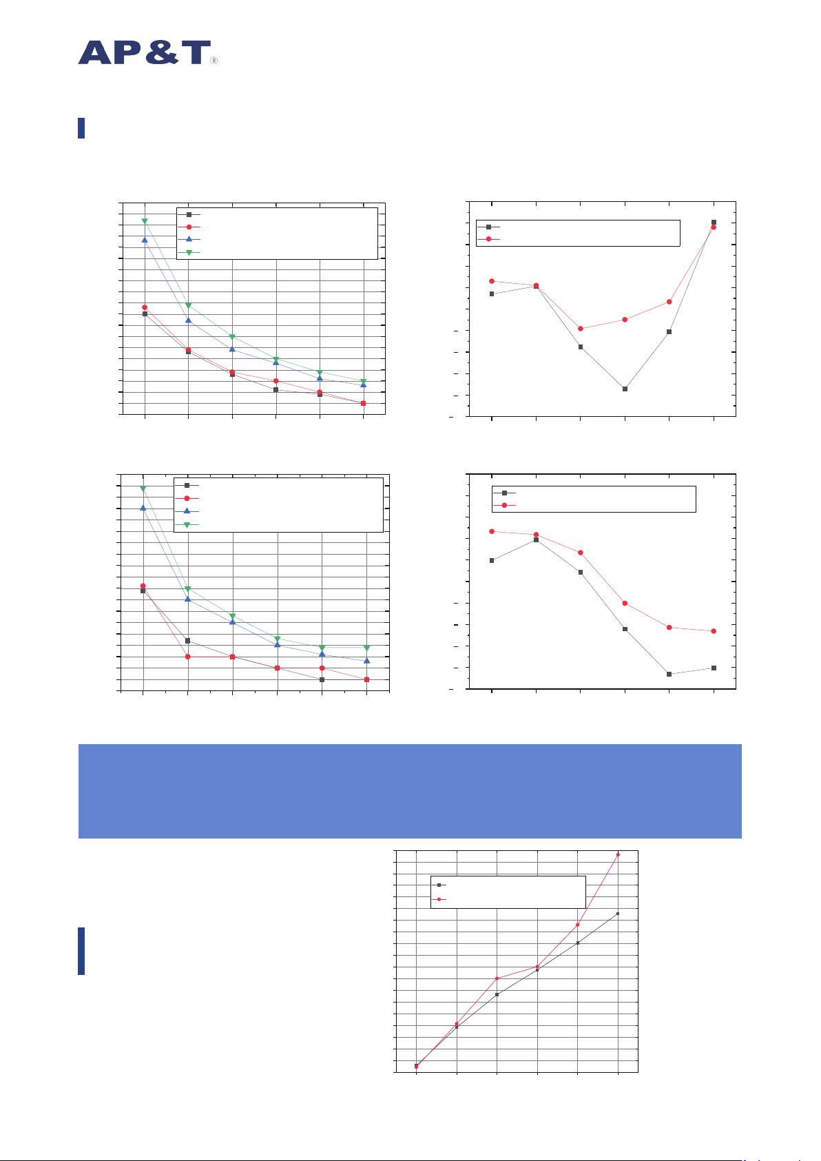
Test Standards:IEC 61340-4-7,ANSI/ESD.STM3.1,SJ/T 11446
Test Instrument:Trek Charged Plate Monitor
Test Voltage:±1000V → ±100V Decay
Test Environment:Relative Humidity:50±5%;Temperature:23±3℃
0.1 0.2 0.3 0.4 0.5 0.6
40
50
60
70
80
90
100
110
120
130
140
150
160
170
180
190
200
210
220
230
∅ 8 Intake Throttle Valve - MAX
∅ 6 Intake Throttle Valve - MAX
Static Elimination Performance Data Chart
Gas Flow Rate
Characteristics
Air Pressure(MPa) Air Pressure(MPa)
Air Pressure(MPa)