ap-az9502-high-frequency-ac-ionizing-air-nozzle-new.pdf - 第6页
0.1 0.2 0.3 0.4 0.5 0.6 10 8 6 4 2 0 2 4 6 8 10 0.1 0.2 0.3 0.4 0.5 0.6 10 8 6 4 2 0 2 4 6 8 10 0.1 0.2 0.3 0.4 0.5 0.6 0.2 0.3 0.4 0.5 0.6 0.7 0.8 0.9 1 1.1 1.2 1.3 1.4 1.5 1.6 1.7 1.8 1.9 2 2.1 0.1 0.2 0.3 0.4 0.5 0.6 …
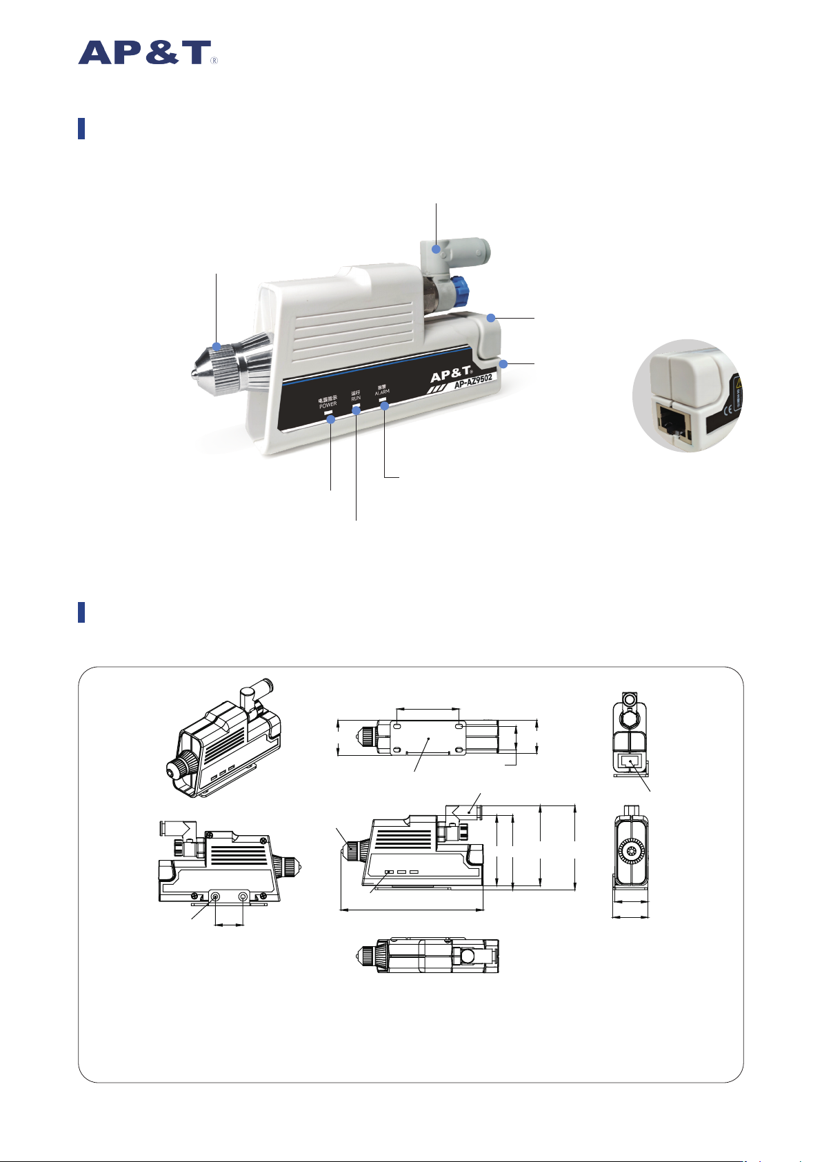
Product Appearance
Product Dimension
Unit:mm
Power Indicator Light -
Green
High Voltage Operation
Abnormal Indicator Light - Red
Discharge Needle High Voltage Box
RJ45 Power Port
Regulating Valve
Air Nozzle Discharge Head / Nozzle
Operation Indicator Light -
Green
25.5
25.5
103
51 54
58.25 61.25
45
17
24
24
20
①
⑥
③
④
⑤
②
① Air Nozzle Discharge Head / Nozzle
② RJ45 Power Port
③ Working Status Indicator Light
④ ∅ 6Intake Throttle Valve
⑤ Mounting Bracket
⑥ M3 Fixing Hole
0.1 0.2 0.3 0.4 0.5 0.6
10
8
6
4
2
0
2
4
6
8
10
0.1 0.2 0.3 0.4 0.5 0.6
10
8
6
4
2
0
2
4
6
8
10
0.1 0.2 0.3 0.4 0.5 0.6
0.2
0.3
0.4
0.5
0.6
0.7
0.8
0.9
1
1.1
1.2
1.3
1.4
1.5
1.6
1.7
1.8
1.9
2
2.1
0.1 0.2 0.3 0.4 0.5 0.6
0.2
0.3
0.4
0.5
0.6
0.7
0.8
0.9
1
1.1
1.2
1.3
1.4
1.5
1.6
1.7
1.8
1.9
2
2.1
Static Decay Time(s)
Ion Balance(V
)
Static Decay Time(s)
Ion Balance(V
)
Air Pressure(MPa) Air Pressure(MPa)
∅
8 Intake Throttle Valve -t+:150mm Test Distance
∅
8 Intake Throttle Valve-t-:150mm Test Distance
∅
8 Intake Throttle Valve -t+:300mm Test Distance
∅
8 Intake Throttle Valve -t-:300mm Test Distance
∅
8 Intake Throttle Valve -Bal:150mm Test Distance
∅
8 Intake Throttle Valve -Bal:300mm Test Distance
Gas Flow Rate(L/min)
∅
6 Intake Throttle Valve -t+:150mm Test Distance
∅
6 Intake Throttle Valve-t-:150mm Test Distance
∅
6 Intake Throttle Valve -t+:300mm Test Distance
∅
6 Intake Throttle Valve -t-:300mm Test Distance
∅
6 Intake Throttle Valve -Bal:150mm Test Distance
∅
6 Intake Throttle Valve -Bal:300mm Test Distance
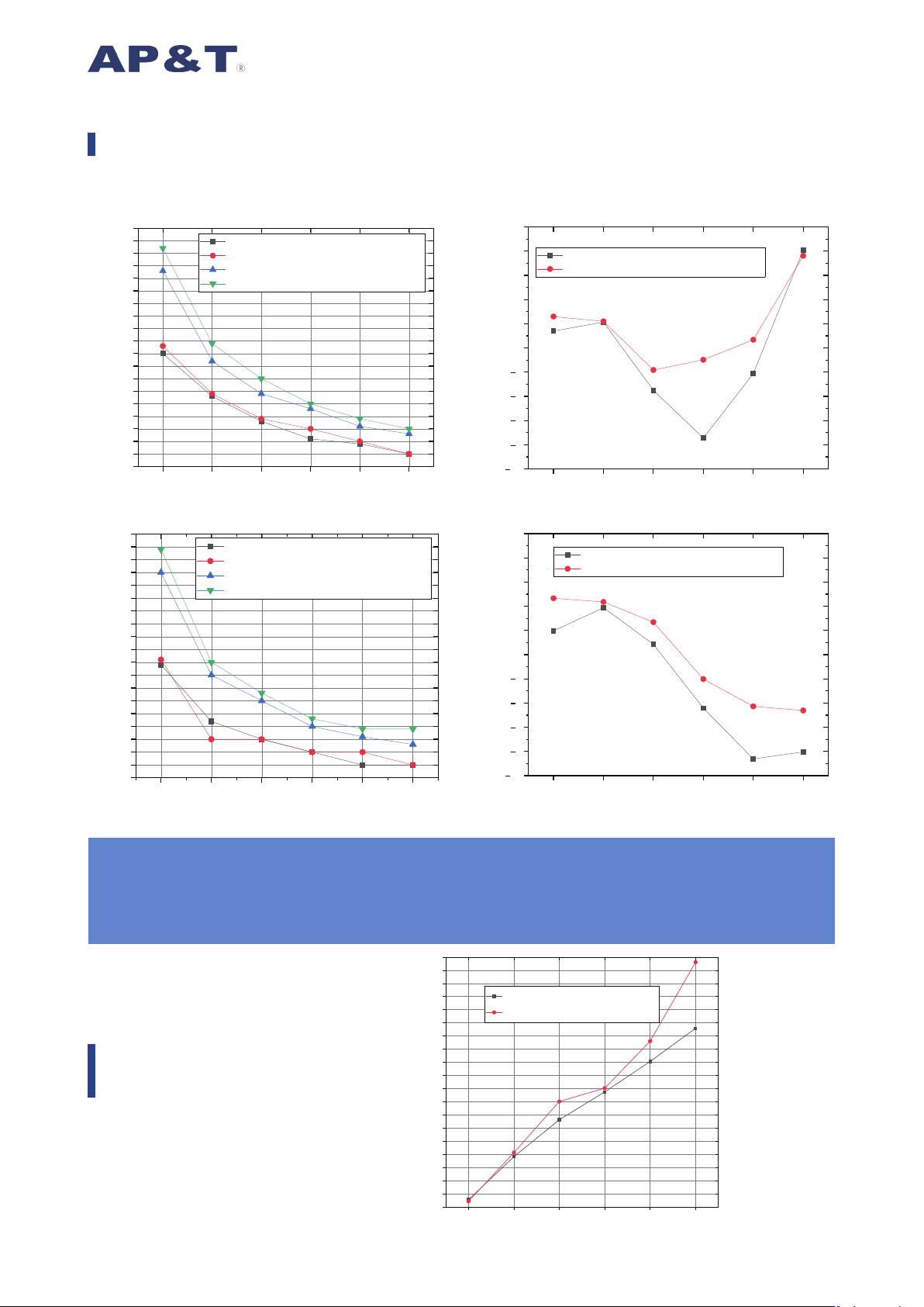
Test Standards:IEC 61340-4-7,ANSI/ESD.STM3.1,SJ/T 11446
Test Instrument:Trek Charged Plate Monitor
Test Voltage:±1000V → ±100V Decay
Test Environment:Relative Humidity:50±5%;Temperature:23±3℃
0.1 0.2 0.3 0.4 0.5 0.6
40
50
60
70
80
90
100
110
120
130
140
150
160
170
180
190
200
210
220
230
∅ 8 Intake Throttle Valve - MAX
∅ 6 Intake Throttle Valve - MAX
Static Elimination Performance Data Chart
Gas Flow Rate
Characteristics
Air Pressure(MPa) Air Pressure(MPa)
Air Pressure(MPa)
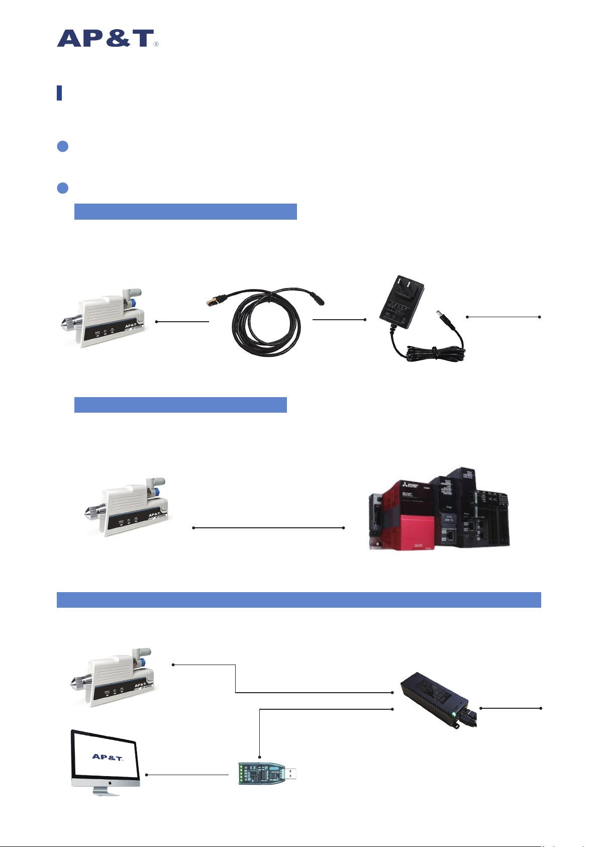
Before use, insert the Φ6mm compressed air hose into the air connector port with throttle valve at the rear
of the air nozzle, ensuring it cannot be pulled out.
The product can be powered according to actual requirements, with the following specific methods:
Insert the RJ45 plug of the power adapter cable into the RJ45 Ethernet port socket on the air nozzle, then
connect the other end of the power adapter cable to the power adapter plug provided by our company, and
connect to mains power AC220V or 110V. As shown in the figure below:
Product Usage Steps
2
1
(1)Without Communication Requirements
Use our company's RJ45 Ethernet port power cable, and connect to the PLC according to the "Ethernet Port
Pinout Function Information Table" to enable monitoring functions.
Note: RS485 and I/O cannot be used simultaneously. As shown in the gure below:
(2)PLC Connection Method:IO/RS485
AP-AZ9502
RJ45 Plug - DC5521 Female
220V
Power Adapter
Custom Ethernet Cable
(Loose Wire End)
Custom Ethernet Cable
(Loose Wire End)
Custom Ethernet Cable
(Loose Wire End)
If only DC24V power supply is
required, this method can be
referenced
AP-AZ9502 PLC
IO Control / RS485
Use our RJ45 power interface and connect to the upper computer via a USB-RS485 converter.
As shown in the diagram below:
(3)Connect to the upper-computer monitoring system (e.g., IMS ionization monitoring system)
AP-AZ9502
Power Adapter
Upper-computer monitoring system
USB to 485
220V