ap-az9502-high-frequency-ac-ionizing-air-nozzle-new.pdf - 第8页
If wiring is required, please r efer to the wiring information table f or connection operations: 3 Adjust the thr ottle valve of the air connect or; the gas pressure should be < 0.5MP a, with the optimal gas pressure …
Before use, insert the Φ6mm compressed air hose into the air connector port with throttle valve at the rear
of the air nozzle, ensuring it cannot be pulled out.
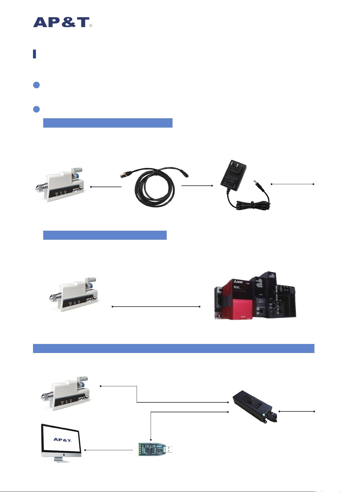
The product can be powered according to actual requirements, with the following specific methods:
Insert the RJ45 plug of the power adapter cable into the RJ45 Ethernet port socket on the air nozzle, then
connect the other end of the power adapter cable to the power adapter plug provided by our company, and
connect to mains power AC220V or 110V. As shown in the figure below:
Product Usage Steps
2
1
(1)Without Communication Requirements
Use our company's RJ45 Ethernet port power cable, and connect to the PLC according to the "Ethernet Port
Pinout Function Information Table" to enable monitoring functions.
Note: RS485 and I/O cannot be used simultaneously. As shown in the gure below:
(2)PLC Connection Method:IO/RS485
AP-AZ9502
RJ45 Plug - DC5521 Female
220V
Power Adapter
Custom Ethernet Cable
(Loose Wire End)
Custom Ethernet Cable
(Loose Wire End)
Custom Ethernet Cable
(Loose Wire End)
If only DC24V power supply is
required, this method can be
referenced
AP-AZ9502 PLC
IO Control / RS485
Use our RJ45 power interface and connect to the upper computer via a USB-RS485 converter.
As shown in the diagram below:
(3)Connect to the upper-computer monitoring system (e.g., IMS ionization monitoring system)
AP-AZ9502
Power Adapter
Upper-computer monitoring system
USB to 485
220V
If wiring is required, please refer to the wiring information table for connection operations:
3
Adjust the throttle valve of the air connector; the gas pressure should be < 0.5MPa, with the optimal gas
pressure being 0.3MPa.
After powering on, ionized gas will be emitted from the nozzle of the air nozzle. If the power-on indicator and
operation indicator on the air nozzle are lit green, it indicates normal operation and electrostatic elimination is
in progress.
The outlet of the ionizing air nozzle should be vertically aligned with the surface of the object to be neutralized of
static electricity, with an optimal distance of approximately 150mm to 300mm.
The compressed air used should be dry and clean.
5
6
7
4
AP-AZ9502-485 AP-AZ9502-IO
Function information of the RJ45 interface cable
1 Orange +24VDC +24VDC
2 White Orange +24VDC +24VDC
3 Blue RS485+B /
4 White Blue RS485+A Input 0V: Ionizer pauses operation
5 Green 0VDC 0VDC
6 White Green 0VDC 0VDC
7 Brown HV
AL
High Voltage Abnormal HV
AL
High-voltage fault
8 White Brown
ACT:Static Eliminator Power-on Indication /
Clean:Static Eliminator Cleaning Indication /
9 Metal Shield PE PE
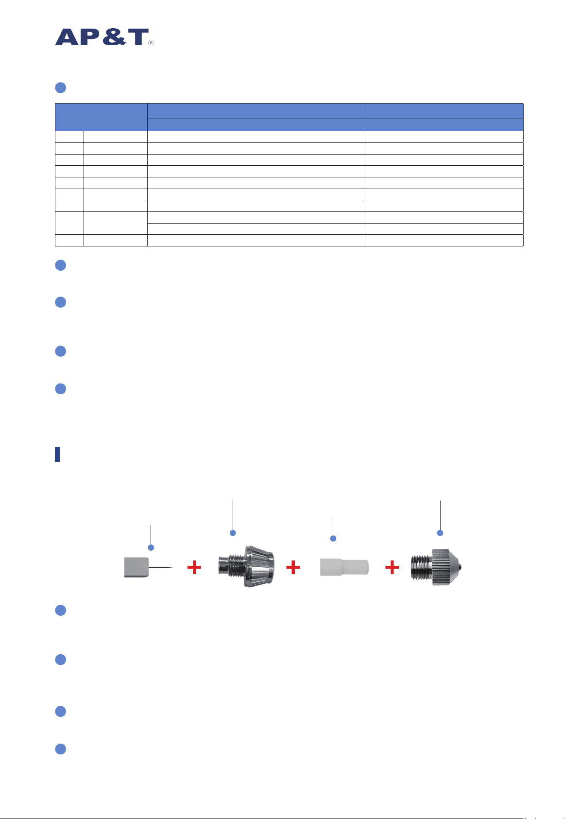
As shown in the figure above, sequentially remove the stainless steel nozzle head and the ceramic protection
tube from the ionizing air nozzle outlet. Observe the exposed alloy electrode; if it appears rounded or blunt,
it should be replaced to ensure the effectiveness of static elimination.
If the green power-on indicator on the air nozzle body goes out or the red alarm indicator lights up, stop
using it. It can only be used again after professional maintenance personnel have checked the circuit or
repaired the air nozzle.
If there is leakage in the air supply hose or throttle valve, check the assembly and connection. If damaged,
replace them promptly to ensure normal air supply pressure.
The alloy electrode in the nozzle part of the air nozzle is a consumable item and is not covered by the
warranty. If replacement is required during maintenance, it will be charged.
Hook Alloy Discharge Needle
Discharge Needle Holder
Ceramic Protection Tube
Nozzle Head
2
3
4
1
Product Maintenance

The AP-AZ9502 High-Frequency Ionizing Nozzle undergoes rigorous testing, inspection, and high-temperature
aging processes before leaving the factory, and its performance fully meets the relevant indicators stated in
the instruction manual.
Anping Company makes the following commitment to users: Within one year from the date of user purchase,
the company will repair or replace free of charge any components found to be defective upon inspection
by the company. After one year, only the cost of parts will be charged, with labor fees waived entirely. This
commitment does not apply under the following circumstances: the equipment has been modified, misused,
disassembled/reassembled by the user, or repaired by other service departments.
Except for the component repair or replacement specified herein, AP&T shall not bear any responsibility
arising from product misuse or accidents.
Before installing and using this equipment, please read the instruction manual carefully.
This equipment should not be used in environments with >70% humidity.
It is strictly prohibited to use this equipment in flammable and explosive environments.
Unauthorized disassembly of the product is strictly prohibited. Internal maintenance and repairs must be
performed by qualified personnel.
The product must not come into contact with conductive liquids, otherwise malfunctions may occur, leading
to electric shock or fire.
When inspecting or replacing the product, the power must be turned off, otherwise it may cause electric
shock or fire.
The product is specifically designed for static elimination. Using it for other purposes is strictly prohibited. Any
improper use may cause machine failure, electric shock, fire, or other hazards.
When the power is on, it is strictly forbidden to touch the electrode needle, as this can easily cause
malfunctions and electric shock accidents.
The electrode needle is a sharp metal object; please handle with care.
Before powering on the product, please check the specifications of the provided power supply. Any power
supply that does not meet the specifications may cause damage or even failure to the product.
Please regularly inspect the product's power cord. If it is damaged, replace it immediately, otherwise it may
easily cause electric leakage, operational abnormalities, and other issues.
When using the air nozzle, a compressed air purification and filtration device should be installed at the air
source connection to ensure the gas entering the nozzle body is dry and clean. This prevents moisture,
oil, etc., from the air source from entering the nozzle area and causing high-voltage short circuits, product
damage, and affecting normal use (recommended pressure dew point ≤ -20° C).
Safety Warnings
After-Sales Service