TS7000-user-guide.pdf - 第4页
4 2. UNPACKING AND INSPECTION Carefully unpack the valve and examine the items contained in the carton . Inspect the unit f or any dam aged which may h ave occurred in transit. If such damage has occurred, notify the car…
14
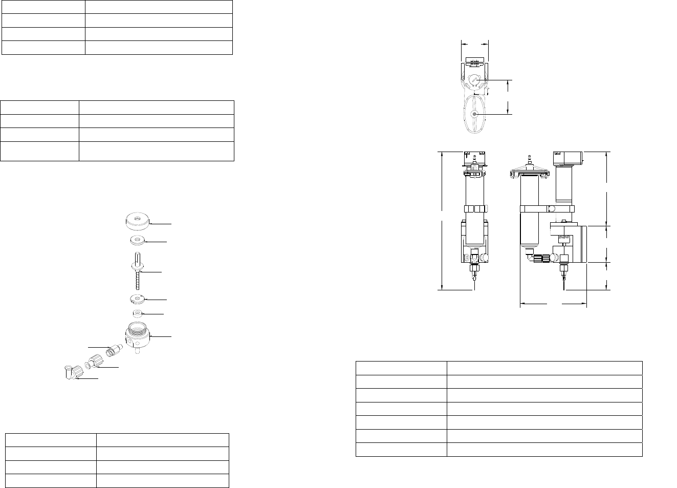
Table #2 Cartridge Assembly Option
Part Number Description
7090-9040 Cartridge Assembly, 16-Pitch
7090-9030 Cartridge Assembly, 8-Pitch
7090-9050 Cartridge Assembly, 8-Pitch HO
Table #3 Needle Retainer Option
Part Number Description
7090-0170 Locking Cap, Metal Needle
7090-0030 Locking Cap, TE Needle
5440-000-004
Locking Cap, TE Needle (Full UV
Block)
12.2 SPARE PARTS: CARTRIDGE ASSEMBLY
Table #4 Feed Screw Option
Part Number Description
7090-0100 Feed Screw, 8-Pitch
7090-0110 Feed Screw, 16-Pitch
7090-0120 Feed Screw, 8-Pitch HO
7090-0090
See Table # 4 below
7090-0130
7090-0140
3300-0353
See Table # 5 below
TSD931-63
TSD931-82
TSD931-81
3
1. SPECIFICATIONS
Motor Voltage: 6-Watt, 24 VDC, 400 RPM
Weight: 0.86 lb (0.40 kg)
Wetted parts: Hardened Tool Steel, Stainless Steel, UHMWPE
Feed screw size options: 16-pitch, 8-pitch, High Output 8-pitch
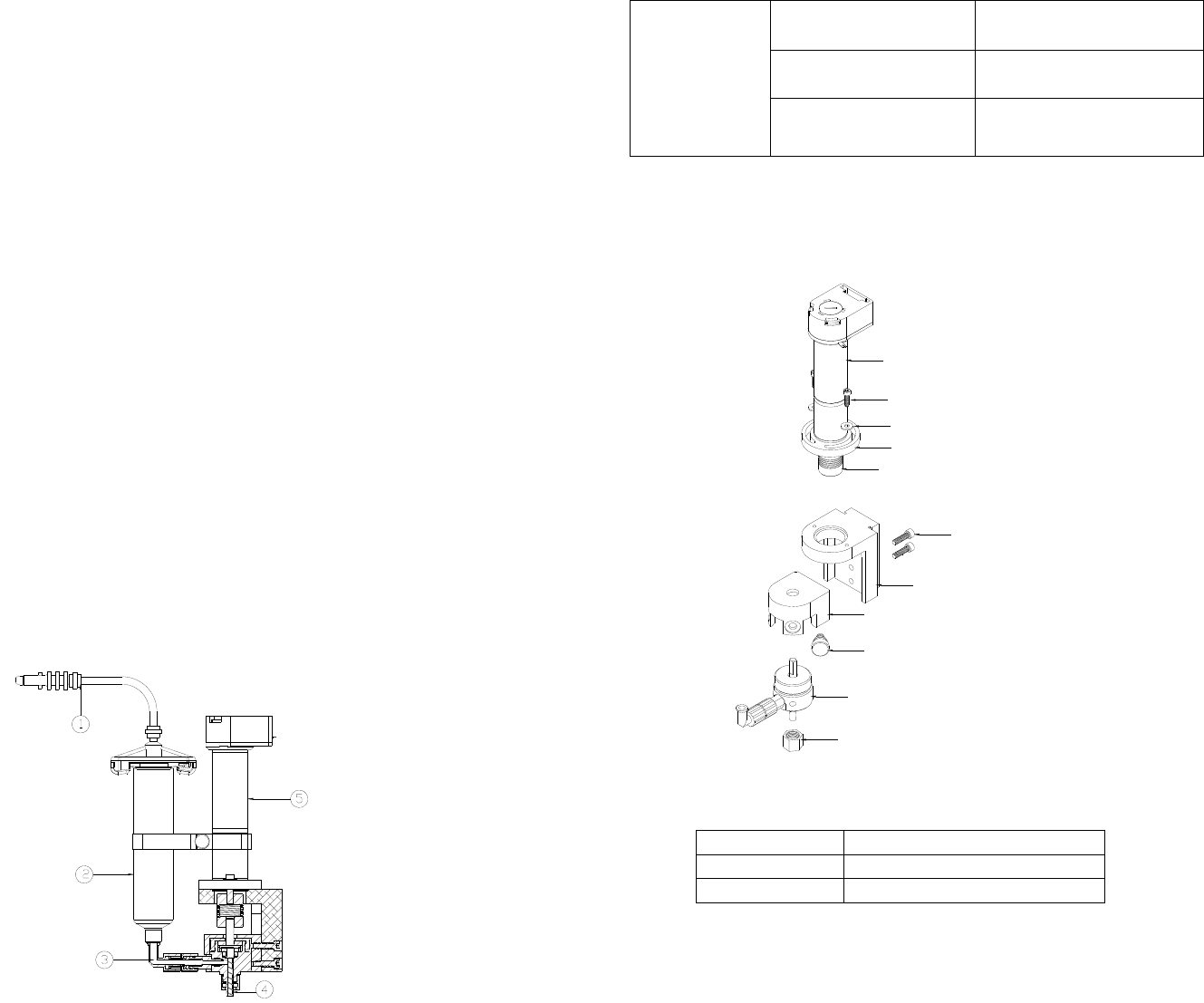
Figure 1.0
Available Configurations:
PART NUMBER DESCRIPTION
TS7000-16 IMP Rotary Valve, 16-Pitch
TS7000-8 IMP Rotary Valve, 8-Pitch
TS7000-8HO IMP Rotary Valve, 8-Pitch High Output
TS7000E-16 IMP Rotary Valve, 16-Pitch, Encoder
TS7000E-8 IMP Rotary Valve, 8-Pitch, Encoder
TS7000E-8HO IMP Rotary Valve, 8-Pitch High Output, Encoder
4.2"(106.7mm)
1.9"(48.3mm)
2.0"(50.8mm)
1.5"(38.1mm)
7
.7"(195.6mm)
1.5"
(38.1mm)
3.7"
(94mm)
4
2. UNPACKING AND INSPECTION
Carefully unpack the valve and examine the items contained in the carton.
Inspect the unit for any damaged which may have occurred in transit. If such
damage has occurred, notify the carrier at once.
3. DESCRIPTION
The TS7000 series Cartridge Rotary Valves are the latest addition to the Rotary
Microvalve family. The valve uses a feed screw (auger) to dispense material
with a rotary displacement action, allowing ultra-precise control of the
dispensing process. The valve’s modular design allows quick and easy
replacement of feed screw/chamber cartridge without the need of removing the
main valve from the machine. In addition, the valve can be interchanged to
use with TS5000DMP feed screw inserts.
The TS7000 series valve is available in 3 choices of feed screw sizes (16-pitch,
8-pitch and high output 8-pitch), all made of precision hardened tool steel.
Encoder motor version available for applications required closed-loop motor
control with encoder feed back.
4. THEORY OF OPERATION
The TS7000 Series Rotary Microvalve dispenses material with a rotary
displacement action using a rotary feed screw principle. Material is held in a
feed reservoir (2) under a positive head of air pressure, between 1 to 30 psi,
depending upon the viscosity of the material. This positive air pressure,
supplied by the air line (1), forces the material out of the barrel (2) into the
material feed path (3) then to the feed screw/chamber assembly (4). Material
flows from this point (4) to the dispense needle outlet is controlled by the feed
screw rotation in the feed direction. The feed screw is driven by the DC motor
(5). Applying a DC voltage signal to the DC motor (5), will rotate the feed
screw and the material will be forced out the dispense tip. The actual material
deposited is dependent upon adhesion of the dispensed material to the substrate.
Shearing of the material is achieved by reverse Z-motion (tip retraction). When
the motor stops, the unit remains in position for a fraction of a second (dwell)
to allow the last drop of material to flow out of the dispense tip. After the
dwell period, the automation equipment moves the valve to the next position.
Figure 2.0
13
Dispense tip
clogged
Tip contacting substrate Increase dispense tip height
Tip bent or damaged Replace tip
Particles size in material too
big
Replace with larger ID tip
12. SPARE PARTS AND ACCESSORIES
12.1 SPARE PARTS: COMPLETE VALVE ASSEMBLY
Table #1 Motor Option
Part Number Description
TSD1412-22 Motor, 6W, 400RPM
TSD1412-31 Encoder Motor, 6W, 400RPM
7090-0040
7090-0020
7090-0050
7090-0010
2800-0213
7090-0060
2800-0423
See Table #1 below
See Table #2 below
See Table #3 below
TSD1109-1
12
11. TROUBLESHOOTING
PROBLEM POSSIBLE CAUSE CORRECTION
No Material Flow
Dispense tip is plugged Replace tip
Motor does not receive
signal
Make sure all connections are
secured
Motor running in reverse
Reverse motor cable
connection
Barrel of dispense material
is emptied
Replace with new material
barrel
Material feed pressure is too
low
Increase feed pressure.
Material dried or cured
Replace with new fresh
material
Inconsistent
Shot size
Material pressure
fluctuating
Make sure material pressure is
constant
Valve on time is too short Increased valve on time
Excessive motor reverse
time
Reduce reverse time or turn off
completely.
Air trapped in material Purge valve properly
Feed screw damaged Replace feed screw
Skipped dots Air trapped in material De-air material
Material drools
after the valve
turned off
Air trapped in feed screw
chamber
Purge valve properly
Air trapped in material
reservoir
Remove air from reservoir
Excessive material feed
pressure
Reduce pressure or turn off
pressure when the valve is
idled.
5
5. SETUP INSTRUCTIONS
5.1 Mechanical Mounting:
Normally, the TS7000 valve is used on an automated XYZ table with full
motion control in the three planes. It is very important that the valve be
mounted on the Z-axis gantry in a secure manner that will not allow
loosening during dispense operation. The Z-axis must move in a precise
and repeatable motion for successful dispensing.
The provided mounting bracket, or customer supplied bracket, must be
attached to the Z-axis in a manner that will provide the valve
perpendicular travel to the horizontal plane of the surface on which the
material will be dispensed. The mounting should provide a means of
accurately adjusting the gap between the dispense tip and the substrate
surface such as a touchdown sensing device or a fixed distance standoff.
5.2 Electrical Connection:
The TS7000 series valve requires an electrical connection of two wires
for the DC motor. The motor lead wires are 24” long. The black lead
wire should be connected to the negative or neutral lead from the motor
control voltage source. To verify the connection, check the rotation
direction of the feed screw. When correctly connected, a positive voltage
signal will drive the feed screw in a counter clockwise direction when
viewed from the dispense tip end.
The recommended controller for the TS7000 series valve is the TS500R.
If another controller is used make sure the control voltage signal is
precisely controlled. The signal should be from a regulated power supply
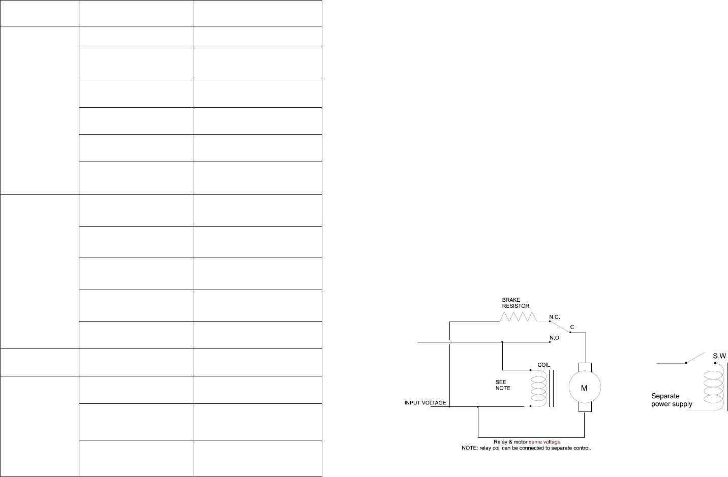
and should be shunted to positive motor stop. Below is a diagram of a
simple braking circuit:
Figure 3.0