TS7000-user-guide.pdf - 第5页
12 11. TROUBLESHOOTING PROBLEM POSSIBLE CAUSE CORRECTION No Material Flow Dispense tip is plugged Replace tip Motor does not receive signal Make sure all connections ar e secured Motor running in reverse Reverse motor ca…
4
2. UNPACKING AND INSPECTION
Carefully unpack the valve and examine the items contained in the carton.
Inspect the unit for any damaged which may have occurred in transit. If such
damage has occurred, notify the carrier at once.
3. DESCRIPTION
The TS7000 series Cartridge Rotary Valves are the latest addition to the Rotary
Microvalve family. The valve uses a feed screw (auger) to dispense material
with a rotary displacement action, allowing ultra-precise control of the
dispensing process. The valve’s modular design allows quick and easy
replacement of feed screw/chamber cartridge without the need of removing the
main valve from the machine. In addition, the valve can be interchanged to
use with TS5000DMP feed screw inserts.
The TS7000 series valve is available in 3 choices of feed screw sizes (16-pitch,
8-pitch and high output 8-pitch), all made of precision hardened tool steel.
Encoder motor version available for applications required closed-loop motor
control with encoder feed back.
4. THEORY OF OPERATION
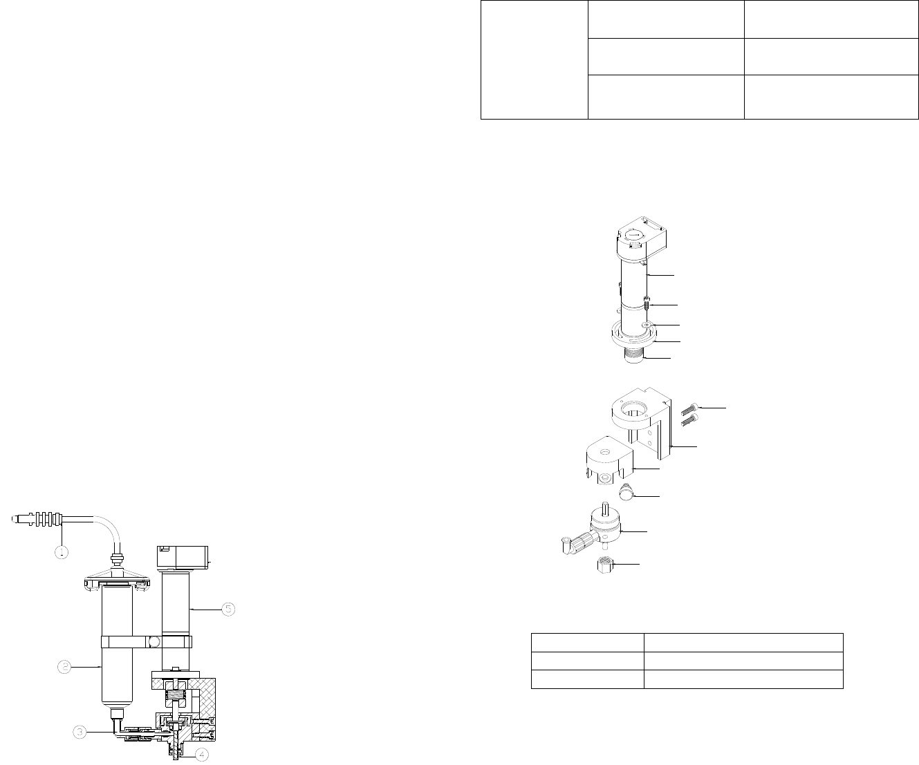
The TS7000 Series Rotary Microvalve dispenses material with a rotary
displacement action using a rotary feed screw principle. Material is held in a
feed reservoir (2) under a positive head of air pressure, between 1 to 30 psi,
depending upon the viscosity of the material. This positive air pressure,
supplied by the air line (1), forces the material out of the barrel (2) into the
material feed path (3) then to the feed screw/chamber assembly (4). Material
flows from this point (4) to the dispense needle outlet is controlled by the feed
screw rotation in the feed direction. The feed screw is driven by the DC motor
(5). Applying a DC voltage signal to the DC motor (5), will rotate the feed
screw and the material will be forced out the dispense tip. The actual material
deposited is dependent upon adhesion of the dispensed material to the substrate.
Shearing of the material is achieved by reverse Z-motion (tip retraction). When
the motor stops, the unit remains in position for a fraction of a second (dwell)
to allow the last drop of material to flow out of the dispense tip. After the
dwell period, the automation equipment moves the valve to the next position.
Figure 2.0
13
Dispense tip
clogged
Tip contacting substrate Increase dispense tip height
Tip bent or damaged Replace tip
Particles size in material too
big
Replace with larger ID tip
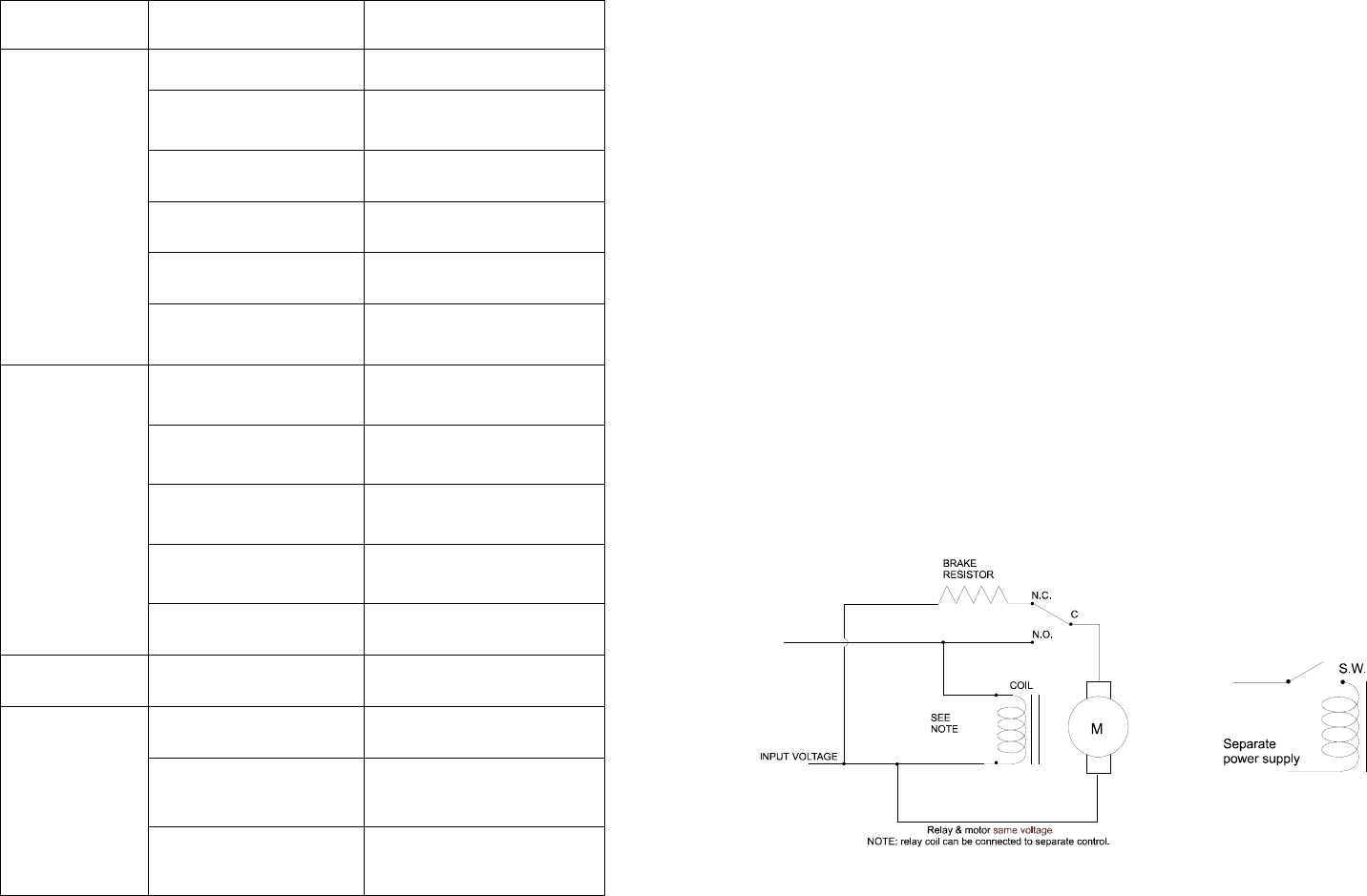
12. SPARE PARTS AND ACCESSORIES
12.1 SPARE PARTS: COMPLETE VALVE ASSEMBLY
Table #1 Motor Option
Part Number Description
TSD1412-22 Motor, 6W, 400RPM
TSD1412-31 Encoder Motor, 6W, 400RPM
7090-0040
7090-0020
7090-0050
7090-0010
2800-0213
7090-0060
2800-0423
See Table #1 below
See Table #2 below
See Table #3 below
TSD1109-1
12
11. TROUBLESHOOTING
PROBLEM POSSIBLE CAUSE CORRECTION
No Material Flow
Dispense tip is plugged Replace tip
Motor does not receive
signal
Make sure all connections are
secured
Motor running in reverse
Reverse motor cable
connection
Barrel of dispense material
is emptied
Replace with new material
barrel
Material feed pressure is too
low
Increase feed pressure.
Material dried or cured
Replace with new fresh
material
Inconsistent
Shot size
Material pressure
fluctuating
Make sure material pressure is
constant
Valve on time is too short Increased valve on time
Excessive motor reverse
time
Reduce reverse time or turn off
completely.
Air trapped in material Purge valve properly
Feed screw damaged Replace feed screw
Skipped dots Air trapped in material De-air material
Material drools
after the valve
turned off
Air trapped in feed screw
chamber
Purge valve properly
Air trapped in material
reservoir
Remove air from reservoir
Excessive material feed
pressure
Reduce pressure or turn off
pressure when the valve is
idled.
5
5. SETUP INSTRUCTIONS
5.1 Mechanical Mounting:
Normally, the TS7000 valve is used on an automated XYZ table with full
motion control in the three planes. It is very important that the valve be
mounted on the Z-axis gantry in a secure manner that will not allow
loosening during dispense operation. The Z-axis must move in a precise
and repeatable motion for successful dispensing.
The provided mounting bracket, or customer supplied bracket, must be
attached to the Z-axis in a manner that will provide the valve
perpendicular travel to the horizontal plane of the surface on which the
material will be dispensed. The mounting should provide a means of
accurately adjusting the gap between the dispense tip and the substrate
surface such as a touchdown sensing device or a fixed distance standoff.
5.2 Electrical Connection:
The TS7000 series valve requires an electrical connection of two wires
for the DC motor. The motor lead wires are 24” long. The black lead
wire should be connected to the negative or neutral lead from the motor
control voltage source. To verify the connection, check the rotation
direction of the feed screw. When correctly connected, a positive voltage
signal will drive the feed screw in a counter clockwise direction when
viewed from the dispense tip end.
The recommended controller for the TS7000 series valve is the TS500R.
If another controller is used make sure the control voltage signal is
precisely controlled. The signal should be from a regulated power supply
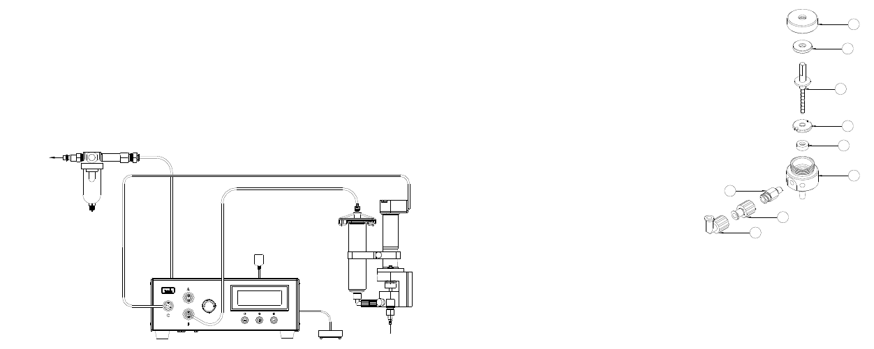
and should be shunted to positive motor stop. Below is a diagram of a
simple braking circuit:
Figure 3.0
6
5.3 Air connection:
Filtered air supply must be precisely regulated and should be set between
1-30 psi, depending on material viscosity. The air supply is not used as
the main dispensing force. It is only required to move the material to the
feed screw chamber.
The valve is supplied with sample of 10 and 30cc air powered syringe
assembly. The syringe of material can be mounted directly onto the
valve inlet fitting. Material can also be supplied from a remotely located
container, such as cartridge systems.
Figure 4.0 Typical Setup Systems
6. DISPENSING APPLICATIONS
6.1 DC Motor Voltage Level:
Voltage controls motor speed (RPM). High voltage produces high motor
speed and low voltage reduces motor speed. Maximum Voltage input is
24 VDC
6.2 Feed screw pitch:
Rate of material dispensed is determined by the pitch of the feed screw. A
high pitch number will produce a low dispense rate and a low pitch
number will produce a higher dispense rate.
6.3 Dispense tip:
The size of the dot diameter or bead width is determined by the dispense
tip. A low gauge number (larger I.D.) will dispense a large diameter dot
or a wide bead. A high gauge number (smaller I.D.) will dispense a
smaller diameter dot or a narrower bead.
Dispense tip sizes smaller than 25-gauge and longer than 1/2" are not
recommended to use with solder paste. A normal rule of thumb to choose
the dispense tip size is that the dot size equal 1.5 times the internal
diameter of the dispense tip.
TS500R CONTROLLER
TS7000 VALVE
TO AIR SOURCE
AIR MUST BE
FILTER AND DRY
11
Figure 7.0
1. Follow steps 1-6 in Section 10.1 “Valve Purging”
2. Follow steps 1- 5 in Section 7.1 “Removing the Cartridge assembly”
3. Remove the Material Inlet Fitting (7) along with the Luer Lock
adapter (8) and Luer Lock Elbow fitting (9) from the Cartridge
4. Remove the Cartridge Cap (1) by turning it counter clockwise
5. Pull the Feed Screw (3) straight out of the Cartridge; Make sure not
to lose the upper bearing washer (2)
6. Using the tweezers (provided in the cleaning kit) to remove the lower
bearing washer (4)
7. Using a cotton swap, carefully remove the seal (5) from the cartridge.
8. Clean all parts using the cleaning brush with any suitable solvent
9. Inspect parts for wear or damage and replace if necessary
10. Re-install the seal (5) into the Cartridge body, make sure the spring
side is facing down
11. Fully press the lower bearing (4) washer into the Cartridge body
12. Insert the Feed Screw (3) into the Cartridge body, make sure not to
damage the seal
13. Install the upper bearing washer (2) on the Feed Screw flange
14. Tighten the Cartridge Cap (1)
15. Install the Material Inlet Fitting (7)
16. Install the Cartridge assembly into valve housing
17. Purge Valve per Section 10.1
1
2
3
4
5
6
8
9
7