Printer 600 Machine Overview.pdf - 第10页
0 $&+,1( 29(59,(: 0 2'8/(29 (59,(:6 3.10 Technical Reference Manual Chapter Issue 4 May 03 Power Supply Module Comprising of th e two major units withi n the machine, the module fulf ills the following funct i…
0$&+,1(29(59,(:
02'8/(29(59,(:6
Chapter Issue 4 May 03 Technical Reference Manual 3.9
Camera and Vision
System Module
The function of the camera and vision system is to supply a visual indication of
screen to board alignment and board and screen inspection data to the vision
card within the machine PC enclosure. The vision card supplies the captured
information to the processor to enable the processor to:
• Utilize the error signal to improve stencil alignment
• Provide visual information for the user on the MMI monitor
When enabled, monitor the printing process to ensure print quality
Screen Change Module
Standard Chase The standard chase enables manual loading and unloading of the print stencils
to the correct position within the chase assembly. With the use of adaptors, the
chase can accommodate the most popular sizes of print stencil.
Adjustable Stencil
Mount
The adjustable stencil mount is a factory fitted chase option enabling manual
loading and unloading of the print stencils to the correct position within the
chase assembly. The module is fully adjustable to accommodate most popular
sizes and thickness of print stencil.
ProFlow Module The ProFlow module is an optional self contained paste transfer unit, employed
to apply solder paste directly to a screen, alleviating the need for squeegees.
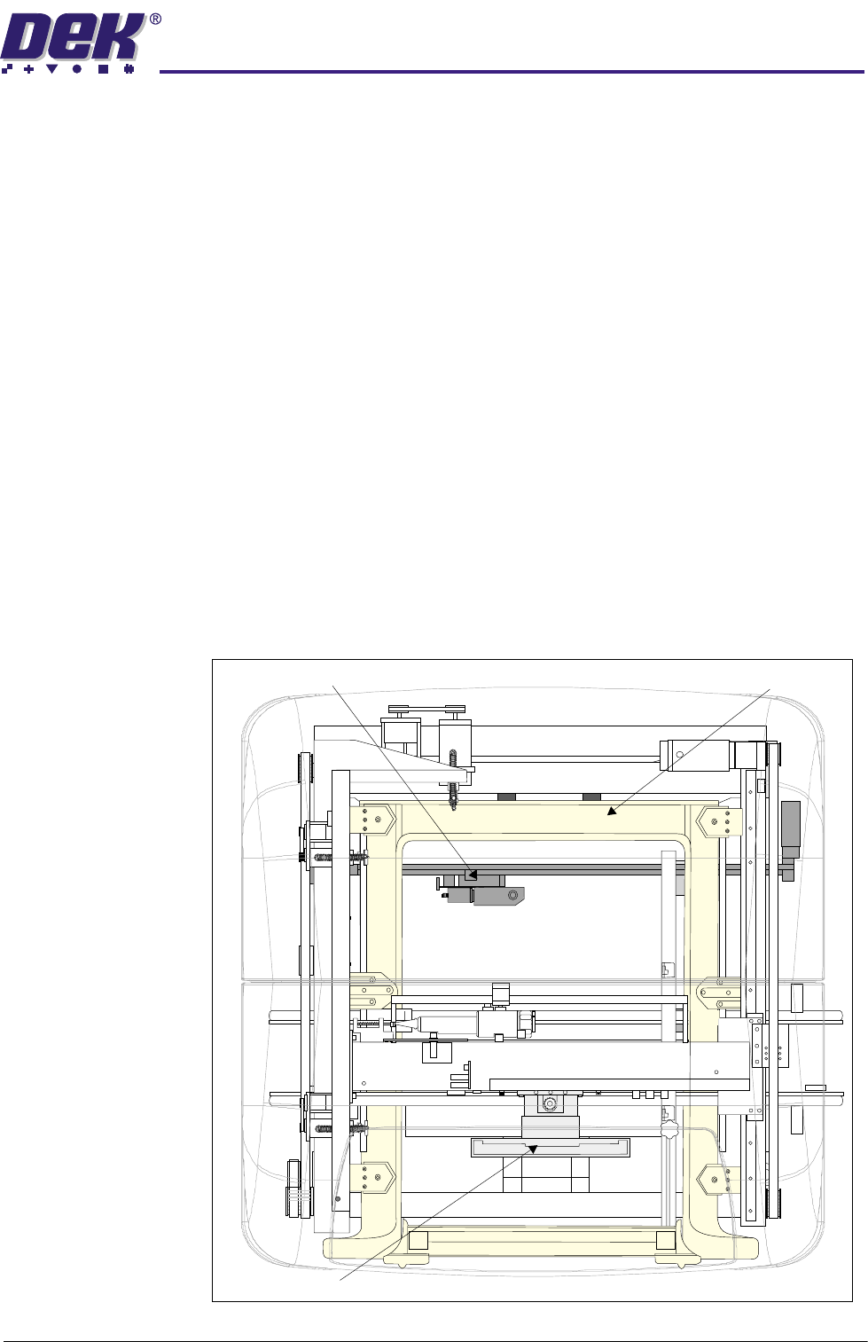
Figure 3-7 Machine Plan View
ProFlow Module
Screen Change Module
Front of Machine
Camera and Vision System Module
TM-6EX
0
$&+,1(29(59,(:
0
2'8/(29(59,(:6
3.10 Technical Reference Manual Chapter Issue 4 May 03
Power Supply
Module
Comprising of the two major units within the machine, the module fulfills the
following functions:
• Transform and rectify the mains voltage supply to the voltages required by
the electrical systems throughout the machine.
• Electrical safety - achieved by the use of emergency stop safety circuits (E
Stop). When an E Stop is activated, power is removed from selected areas
of the machine.
Pneumatics
Module
The function of the pneumatics module is to supply regulated air pressure to the
pneumatic devices throughout the machine. The air supply is routed to the
required pneumatic device via an electrically operated solenoid valve controlled
by the machine controller enclosure.
Under Screen
Cleaner
The under screen cleaner module provides the facility to automatically clean the
underside of the stencil so reducing the build up of paste. The frequency and
mode is programmable in software. The screen cleaner is driven across the
underside of the stencil by the camera carriage.
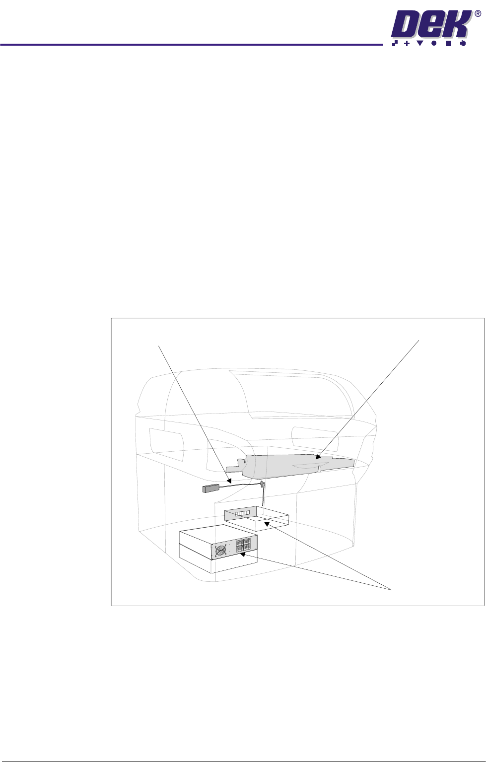
Figure 3-8 Machine Front View
Underscreen Cleaner Module
Power Supply Module
Pneumatics Module
0$&+,1(29(59,(:
02'8/(29(59,(:6
Chapter Issue 4 May 03 Technical Reference Manual 3.11
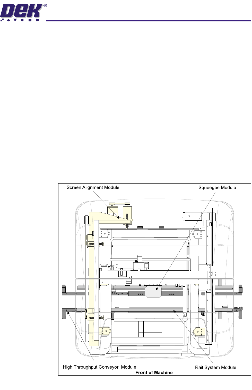
Squeegee Module The function of the squeegee module is to apply the solder paste through the
screen image onto the board in a controlled manner. Squeegee height and
downward pressure is monitored during the print stroke to optimize the print
quality. The paste knead sequence is performed by the squeegee module
utilizing the print carriage.
Screen Alignment
Module
The screen alignment module enables fine adjustment of the print screen to
achieve optimum screen to board alignment prior to the print cycle. Actuators
move the print screen in the X, Y and theta planes to nullify the misalignment
error signal from the vision system. The print screen is clamped into place
during the print cycle.
High Throughput
Conveyor Module
The high throughput conveyor module is an optional programmable width
conveyor system. The function of the HTC is to transport up to three boards
through the machine at one time and security of the board on the print station
during the print stroke.
Rail System
Module
The rail system module is a programmable width conveyor system, utilized to
transport the board through the machine and security of the board during the
print stroke. The rail system is positioned by the rising table, during the print
stroke.
Figure 3-9 Machine Plan View