C371347_139780418F8DFE40697A24CD62AD2CE5.pdf - 第10页
CM108B USB Audio Single C hip Datasheet Revision: 1.11 www .cmedia.com.tw P age 10 / 24 Copyright© C -Media Electr onics Inc. 6 I2S Interface The CM108B provides an I2 S interface for both pl ayback and recording. Extern…
CM108B
USB Audio Single Chip
Datasheet Revision: 1.11 www.cmedia.com.tw
Page 9 / 24 Copyright© C-Media Electronics Inc.
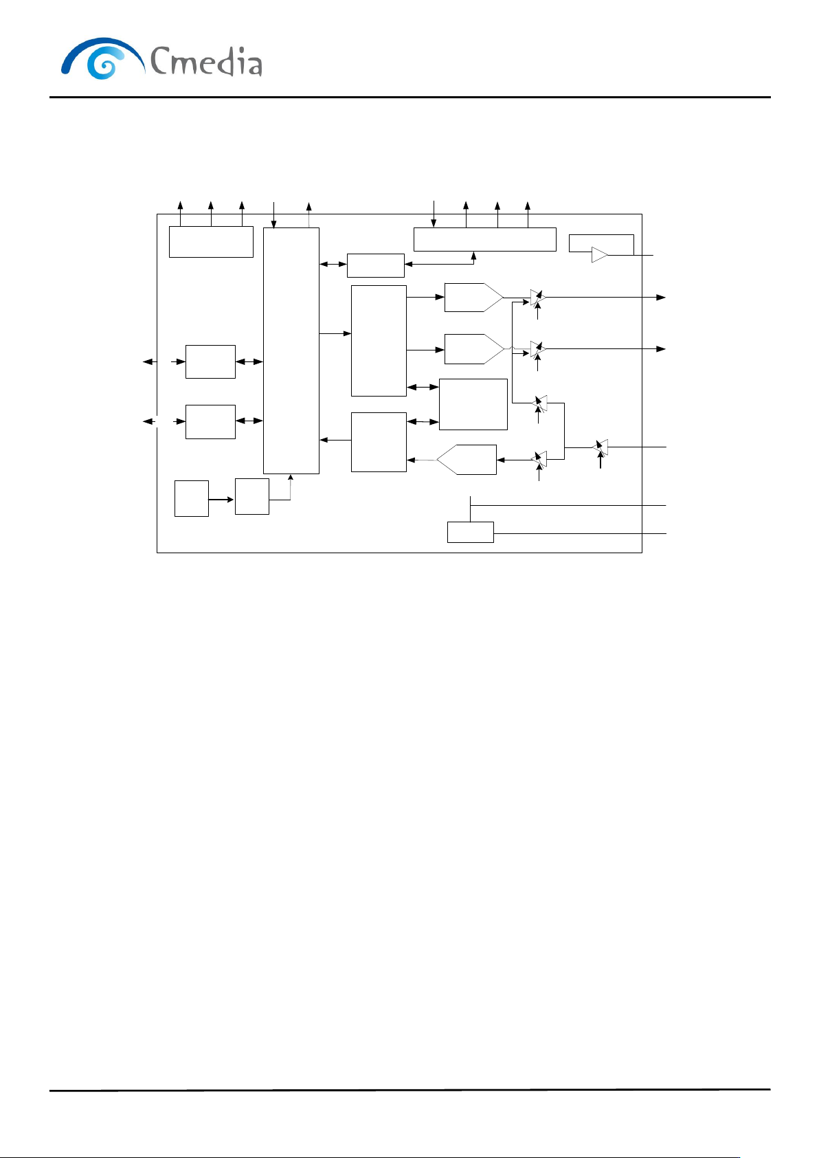
5 Block diagram
Regulator
5->3.6, 3.3 & 1.8
USB
Interface
USB TRX
EEPROM
Interface
RF
PLL
ISO Out
Processing
ISO In
Processing
12M
48M
SPI
USB
DW
DR
SK
CS
USBDP
USBDN
16 bit
DAC
16 bit
DAC
12dB/22dB
Booster
23 ~ -22dB
8 ~ -22dB
0 ~ -45dB
0 ~ -45dB
SRAM
bandgap
VREF
(1.75V)
VREF
VBIAS
(3V)
USB Control
Interface Logics
AREG36
VOLUP
VOLDN
MUTER
MUTEP
LEDO
LEDR
PWRSEL
MODE
MSEL
PDSW
3.6V
LOR
LOL
MICI
N
DREG33
3.3V 1.8V
VREF
LOBS
16 bit
ADC
DREG18
GPIOs
DASCLK/ADSCLK
DALRCK/ADLRCK
DAMCLK/ADMCLK
SDOUT/SDIN
I2S Out/In
CM108B Block Diagram

CM108B
USB Audio Single Chip
Datasheet Revision: 1.11 www.cmedia.com.tw
Page 10 / 24 Copyright© C-Media Electronics Inc.
6 I2S Interface
The CM108B provides an I2S interface for both playback and recording. External ADC, DAC, or DSP can be added to
provide additional functions within the USB audio system. The CM108B sends out master clock (fixed at x256), LRCK
(fixed at x64), and data clock data. Therefore, external ADCs, DACs, or DSPs should be set to slave mode.
The left channel of the CM108B’s I2S bus is used for mono recording. Both IP
2P
S buses use a 5V tolerant pad in order
to easily interface with 5V or 3.3V devices. Playback data is simultaneously sent to both the DAC and I2S bus. The
recording source (ADC or I2S bus) can be selected by ADSEL jumper pin.
LRCK
SCLK
MSB -1 -2 +2 +1 LSB MSB -1 -2 +2 +1 LSB
SDATA
Left Channel
Right Channel
CM108B
USB Audio Single Chip
Datasheet Revision: 1.11 www.cmedia.com.tw
Page 11 / 24 Copyright© C-Media Electronics Inc.
7 Function description
7.1 USB interface
The CM108B integrates USB transceiver, PLL and regulator modules, meaning only a few passive components are
necessary for USB interface connection. Default USB descriptors are embedded in the CM108B, so no additional
design effort is needed for generic USB operation. For custom orders, customers can attach a 93C46 EEPROM to
override the embedded VID, PID, product and manufacturer strings, and initial/max/min volume settings. The
CM108B automatically detects the 93C46, and the overwrite function is performed at start up.
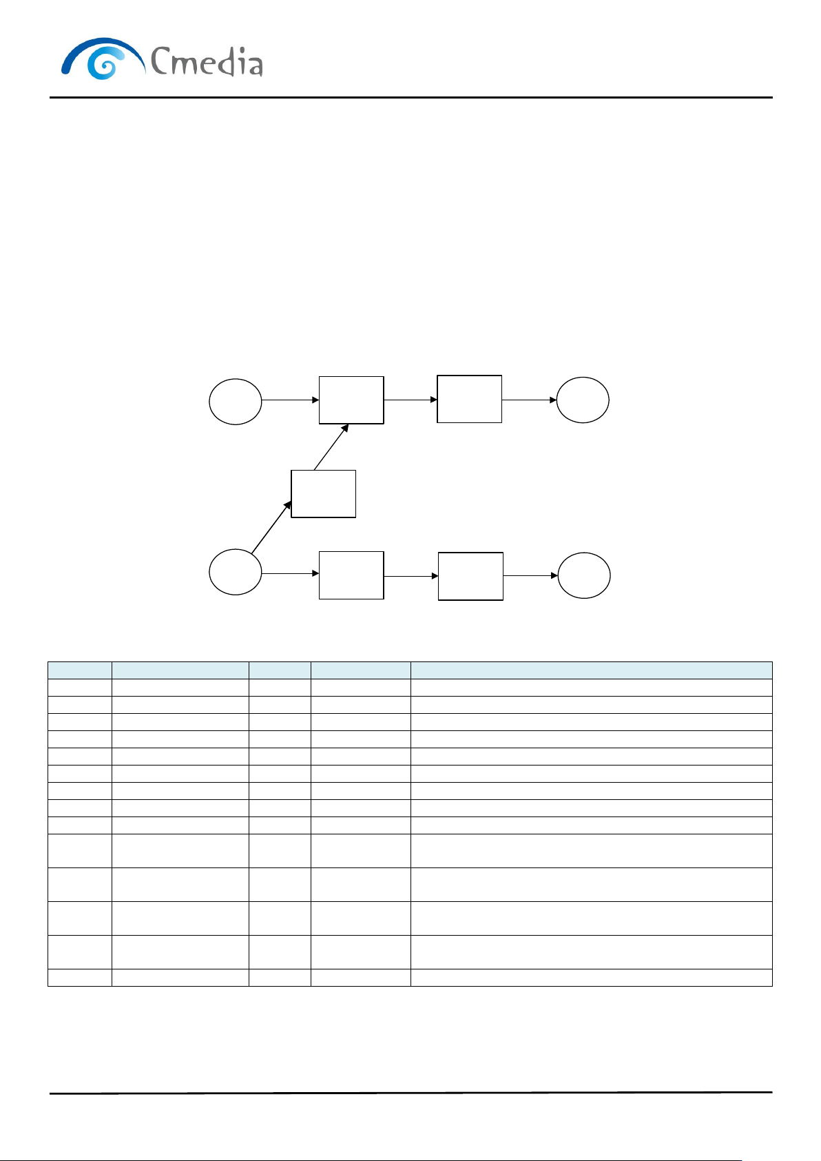
7.1.1 USB audio topology diagram for headset
The CM108B supports headset and speaker topology that can be selected by MODE pin. The topology setting as
following: MODE=0, Headset Topology; MODE=1, Speaker Topology
0X01
IT
0X0F
MIXER
0X09
FEA
0X06
OT
0X02
IT
0X0A
FEA
0X08
SEL
0X07
OT
0X0D
FEA
Device Descriptor
Offset
Field
Size
Value (Hex)
Description
0
bLength
1
12
Total 18 Bytes
1
bDescriptorType
1
01
Device Descriptor
2
bcdUSB
2
0110
USB 1.1 compliant.
4
bDeviceClass
1
00
Device class specified by interface
5
bDeviceSubClass
1
00
Device subclass specified by interface
6
bDeviceProtocol
1
00
Device protocol specified by interface
7
bMaxPacketSize0
1
8
Endpoint zero Size = 8 bytes
8
idVendor
2
0d8c
Vendor ID
10
idProduct
2
0012
Product ID
12
bcdDevice
2
0100
Device compliant to the Audio Device Class specification
version 1.00
14
iManufacturer
1
01
Index of string descriptor describing manufacturer
15
iProduct
1
02
Index of string descriptor describing product
16
iSerialNumber
1
00
Index of string descriptor describing the device’s serial
number
17
bNumConfigurations
1
01
Configurations number = 1
Configuration Descriptor