C371347_139780418F8DFE40697A24CD62AD2CE5.pdf - 第16页
CM108B USB Audio Single C hip Datasheet Revision: 1.11 www .cmedia.com.tw P age 16 / 24 Copyright© C -Media Electr onics Inc. 7.3 HID feature USB protocols can configure devices at startu p or when th ey are plugged in a…

CM108B
USB Audio Single Chip
Datasheet Revision: 1.11 www.cmedia.com.tw
Page 15 / 24 Copyright© C-Media Electronics Inc.
7.2 Jumper pins and mode setting:
The CM108B can be configured via several jumper pins. These jumper pin settings affect both USB descriptors and
USB audio topology.
7.2.1 Mode pin and msel pin
If the MODE pin is pushed up to 3.3V (speaker mode), a playback-only function is activated and no recording function
is declared to the host. At this setting, the MSEL pin is ignored and only one input terminal, one output terminal and
one feature unit is declared in the USB audio topology.
If the MODE pin is pulled low (headset mode), a full-duplex playback and recording function is reported to the host.
The MSEL pin setting activates one mixer unit and one feature unit.
When MSEL = 1, the mixer is enabled (AA-path enabled), but with default mute setting
When MSEL = 0, the mixer is disabled (AA-path disabled)
The above USB audio topology (7.1.4) is an example of headset mode with enabled mixer.
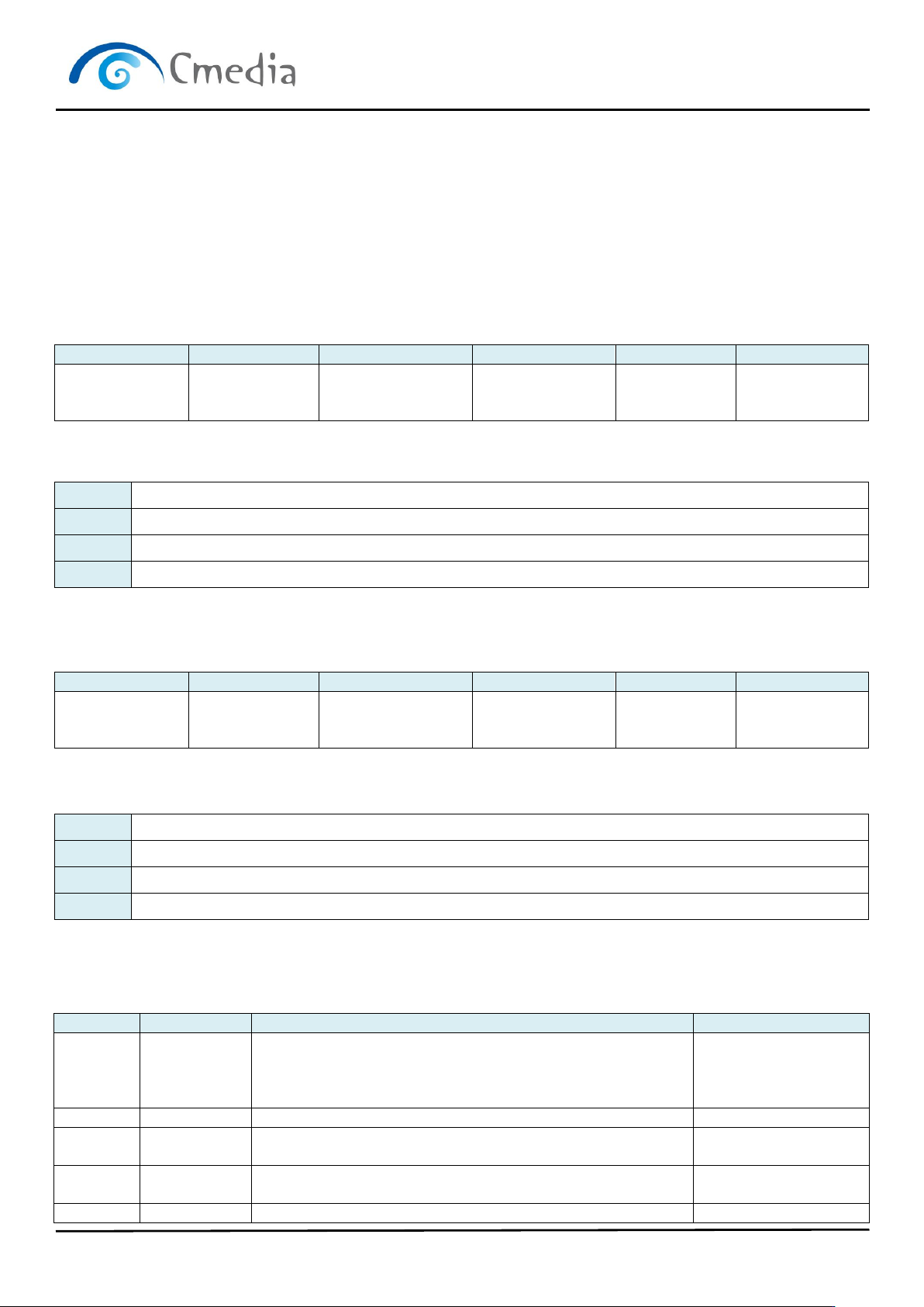
7.2.2 Mode pin and pwrsel pin
The PWRSEL pin affects the power configuration of the CM108B. Together with the MODE pin, there are a total of 4
programmable combinations.
Combinations
MODE
3.3V
GND
PWRSEL
3.3V
Speaker mode:
Playback only
(100mA self-powered)
Headset mode:
Playback and recording
(100mA Bus-powered)
GND
Speaker mode:
Playback only
(500mA Bus-powered)
Headset mode:
Playback and recording
(500mA Bus-powered)
USB Audio Topology Diagram
CM108B
USB Audio Single Chip
Datasheet Revision: 1.11 www.cmedia.com.tw
Page 16 / 24 Copyright© C-Media Electronics Inc.
7.3 HID feature
USB protocols can configure devices at startup or when they are plugged in at run time. These devices are
categorized into various device classes. Each device class defines the common behavior and protocols for devices
that serve similar functions. The HID (Human Interface Device) class is one of the device classes.
The HID class consists primarily of devices that are used to control the operation of computer systems. Typical
examples of HID class devices include:
The CM108B’s HID feature allows users to set volume up, volume down, playback mute and recording mute button
pins, and reports the changes to the host to synchronize host side settings. In addition, all CM108B internal registers
can be accessed via HID function call.
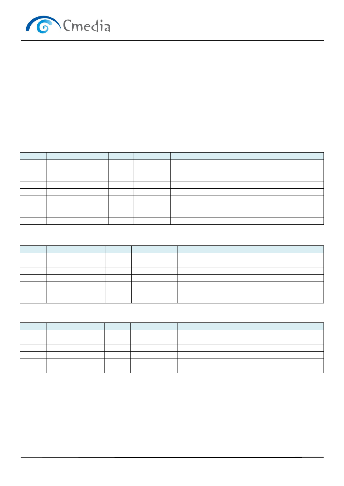
7.3.1 HID descriptors
HID Interface Descriptor
Offset
Field
Size
Value (Hex)
Description
0
bLength
1
09
Size of this descriptor: 9 bytes
1
bDescriptorType
1
04
Interface descriptor type
2
bInterfaceNumber
1
03
Interface number: 3
3
bAlternateSetting
1
00
Alternate: 0
4
bNumEndpoints
1
01
Number of endpoints used by this interface: 1
5
bInterfaceClass
1
03
Interface class: HID
6
bInterfaceSubClass
1
00
Subclass: no
7
bInterfaceProtocol
1
00
Must be set to 0
8
iInterface
1
00
String descriptor index that characterizes this interface
HID Descriptor
Offset
Field
Size
Value (Hex)
Description
0
bLength
1
09
Total: 9 bytes
1
bDescriptorType
1
21
HID descriptor type
2
bcdHID
2
0100
HID class version 1.0
4
bCountryCode
1
00
5
bNumDescriptors
1
01
6
bDescriptorType
1
22
Report descriptor
7
wDescriptorLength
2
003C
Total size of the optional descriptor: 60 bytes
Interrupt IN Endpoint Descriptor
Offset
Field
Size
Value (Hex)
Description
0
bLength
1
07
Total: 7 bytes
1
bDescriptorType
1
05
Endpoint descriptor type
2
bEndpointAddress
1
87
In Endpoint Number = 3
3
bmAttributes
1
03
Interrupt endpoint type
4
wMaxPacketSize
2
0004
Maximum packet size: 4 bytes
6
bInterval
1
2
2ms
CM108B
USB Audio Single Chip
Datasheet Revision: 1.11 www.cmedia.com.tw
Page 17 / 24 Copyright© C-Media Electronics Inc.
7.4 Internal Registers
All of CM108B’s internal registers can be accessed via generic HID functional calls without the need to develop a
kernel mode driver. In total, 4 bytes of data can be read or written from the HID. The input report is for read and the
output report is for write. These internal registers of CM108B are used to control GPIO pins, S/PDIF output and
EEPROM data access.
Access via HID Class Command
HID interrupt will occur when HID_IR0-3 are updated by button status, or GPI in case HID_IR0[7:6] == 2’b00).
HID Get_Input_Report Format
Command Format:
bmRequestType
bRequest
wValue
wIndex
wLength
Data
8’h A1
8’h 01
(Get_Report)
16’h 01 00
(Rpt Type + Rpt ID)
16’h 00 02
16’h 00 03
(Interface)
16’h 00 04
(4 bytes)
Report
Input Data Format:
byte 0
HID IR0[7:0]
byte1
HID IR1[7:0]
byte2
HID IR2[7:0]
byte3
HID IR3[7:0]
HID Set_Output_Report Format
Command Format:
bmRequestType
bRequest
wValue
wIndex
wLength
Data
8’h 21
8’h 09
(Set_Report)
16’h 02 00
(Rpt Type + Rpt ID)
16’h 00 02
16’h 00 03
(Interface)
16’h 00 04
(4 bytes)
Report
Output Data Format:
byte 0
HID OR0[7:0]
byte1
HID OR1[7:0]
byte2
HID OR2[7:0]
byte3
HID OR3[7:0]
HID_IR0 (HID input report byte 0)
Offset: 0x00
Bits
Read/Write
Description
Default
7-6
R
00: HID_IR1 is used as GPI,
10: values written to HID_IR0-3 are also mapped to
EPROM_DATA0-1 and EEPROM_CTRL
Others: reserved
0x0
5-4
R
Reserved
0x0
3
R
0: no activity on record/mute button
1: record/mute button pressed then released
0x0
2
R
0: no activity on playback/mute button
1: playback/mute button pressed then released
0x0
1
R
0: volume-down button released
0x0