TS5000-user-guide.pdf
16 10. SPARE PARTS AND ACCESSORIES 10.1 SPARE PARTS: The only spare parts availabl e are: Fluid inlet fitting, O- ring and clean o ut screw. These items are in cluded in the Valv e cleaning ki t part number: 5000-013-000…
16
10. SPARE PARTS AND ACCESSORIES
10.1 SPARE PARTS: The only spare parts available are: Fluid inlet fitting, O-
ring and clean out screw. These items are included in the Valve cleaning kit
part number: 5000-013-000
10.2 ACCESSORIES
PART NUMBER DESCRIPTION
5000-000-080 Torque wrench for metal valve
5000-000-082 Torque wrench for plastic valve
7105XCON Dispensing conditioner, 10-CC, 700 series syringe
7305XCON Dispensing conditioner, 30-cc, 700 series syringe
11. WARRANTY
Manufacturer warrants this product to the original purchaser for a period of one
(1) year from date of purchase to be free from defects in material and
workmanship, but not against damages by misuse, negligence, accident, faulty
installations and instructions. Manufacturer will repair or replace (at factory’s
option), free of charge, any component of the equipment thus found to be
defective, on return of the component, “PREPAID” to the factory during the
warranty period. In no event shall any liability or obligation of the
Manufacturer arising from this warranty exceed the purchase price of the
equipment. This warranty is only valid if the defective product is returned as a
complete assembly without physical damage. The Manufacturer’s liability, as
stated herein, cannot be altered or enlarged except by a written statement
signed by an officer of the company. In no event shall the Manufacturer be
liable for consequential or incidental damages. A return authorization is
required from Techcon Systems prior to shipping a defective unit to the factory.
Manufacturer reserves the right to make engineering product modifications
without notice.
Send warranty returns to:
OK International
Garden Grove Division
12151 Monarch Street
Garden Grove, Ca 92841
TSI-0118_G
Techcon Systems
TS5000 Series
Rotary Valve
User Guide

2
CONTENTS
Page number
1. Specifications …………………………………………………3
2. Unpacking and inspection……………………………………..4
3. Description……….……………………………………………4
4. Theory of operation….…...……………………………………5
5. Setup instructions
5.1 Mechanical Mounting….……..…………………………6
5.2 Electrical Connection…....………………………………6
5.3 Air Connection ………………………………………7
6. Typical system setup ………………………………………7
7. Dispensing application ………………………………………8
8. Troubleshooting ………………………………………10
9. Maintenance and cleaning
9.1 Valve purging ………………………………………11
9.2 Thorough cleaning ………………………………………12
9.3 Valve reassembly ………………………………………14
9.4 Priming the valve ………………………………………15
10. Spare parts and accessories ……………………………16
11. Warranty …………………………………………………16
15
9.4 Priming the valve:
The valve is shipped with conditioner filled inside valve chamber to ensure the
valve is not run “dry” during initial start-up.
CAUTION: Running the valve dry (without dispense material) may cause
damage to the feed screw and chamber.
1. Attach a barrel of dispensing conditioner (Part number 7305XCON)
to the valve inlet.
2. Apply 8 psi pressure on the barrel and let the pressure push the
conditioner through the valve for 2 minutes. Do not apply more than
10 psi on the conditioner when priming as this may cause compressed
air pockets in the valve chamber.
3. Turn on the motor and let it run until a steady stream of fluid is being
dispensed.
4. Turn off motor.
5. Install appropriate dispense tip to the valve outlet. Do not over
tighten the dispense tip.
Note: Techcon makes available a torque wrench that is designed to
fit Techcon supplied dispense tip. (Part number: 5000-000-080 for
metal valves and 5000-000-082 for Delrin valves)
14
17. Visually inspect the valve body to any foreign material and repeat
cleaning process if necessary.
18. Insert a 0.1255” pin gauge into the valve body from the motor side.
If the pin moves smoothly and easily through the valve body, there
are no detrimental deposits in the valve. If the pin stop or snags,
gently push the pin through the hole to remove any deposits. If the
pin still does not want to move, please return the valve for repair.
19. Insert a 0.1262” pin gauge to into valve body from the motor side. If
the pin goes through the hole, please return the valve for repair.
9.3 Valve re-assembly
1. Reinstall the female luer lock fitting (10) into the valve body. Make
sure to apply some thread sealant on the fitting, such as Loctite 222.
2. Place the O-ring (8) on the clean out screw (9) and reinstall the clean
out screw assembly into the 45
o
feed shaft.
3. Lubricate the O-ring (3) with appropriate O-ring grease such as
Parker O-Lube.
4. Install O-ring (3) to the feed screw.
5. Gently slide the motor/feed screw assembly into the valve body
CAUTION: The fit between the feed screw and the chamber is very precise.
Extreme care must be taken during this operation.
6. Reinstall the two socket head screws (6) into the valve body.
Alternately tighten the screws a little at a time until both are secure.
Do not over tighten as this may distort the mounting plate and miss-
align the feed screw.
3
1. SPECIFICATIONS
Motor options: 2.7-Watt, 6-Watt, 6-Watt with digital encoder
Speed options: 125, 250, 400 RPM
Feed screw size options: 8-pitch standard
8-pitch high output
16-pitch standard
16-pitch shallow
Feed screw material options: Stainless steel
Delrin
Carbide
Feed screw chamber options: Stainless steel
Delrin
Valve body options: Anodized aluminum
Delrin
O-ring options: Viton, EPR
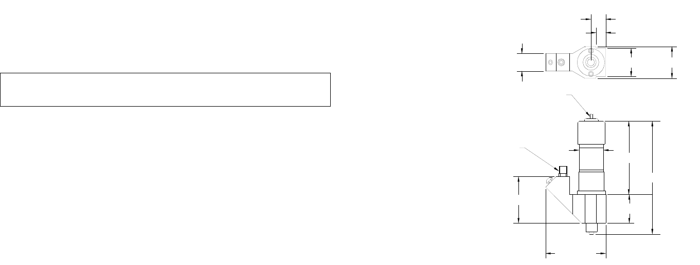
Figure 1.0 Valve with 2.7 Watt Motor
VALVE
TS5000
3.98" (101.0mm)
24" (610mm) LONG CALBE
FLUID INLET
.62" (15.7mm)
.52" (13.2mm)
.34" (8.6mm)
1.12" (28.5mm)1.00" (25.3mm)
2.13" (54.0mm)
2.58" (65.5mm)
1.01" (25.7mm)
.90" (22.9mm)
1.64" (41.7mm)