TS5000-user-guide.pdf - 第7页
10 8. TROUBLESHOOTING PROBLEM POSSIBLE CAUSE CORRECTION No Fluid Flow Dispense tip is plugged Replace tip Motor does not receive signal Make sure all connections are secured Motor running in reverse Reverse motor cable c…
6
5. SETUP INSTRUCTIONS
5.1 Mechanical Mounting:
Normally, the TS5000 valve is used on an automated XYZ table with full
motion control in the three planes. It is very important that the valve be
mounted on the Z-axis gantry in a secure manner that will not allow
loosening during dispense operation. The Z-axis must move in a precise
and repeatable motion for successful dispensing.
The provided mounting bracket, or customer supplied bracket, must be
attached to the Z-axis in a manner that will provide the valve
perpendicular travel to the horizontal plane of the surface on which the
fluid will be dispensed. The mounting should provide a means of
accurately adjusting the gap between the dispense tip and the substrate
surface such as a touchdown sensing device or a fixed distance standoff.
5.2 Electrical Connection:
The TS5000 valve requires an electrical connection of two wires for the
DC motor. The motor lead wires are 24” long. The black lead wire
should be connected to the negative or neutral lead from the motor
control voltage source. To verify the connection, check the rotation
direction of the feed screw. When correctly connected, a positive voltage
signal will drive the feed screw in a counter clockwise direction when
view from the dispense tip end.
The recommended controller for the TS5000 valve is the TS500R. If
another controller is used made sure the control voltage signal is
precisely control. The signal should be from a regulated power supply
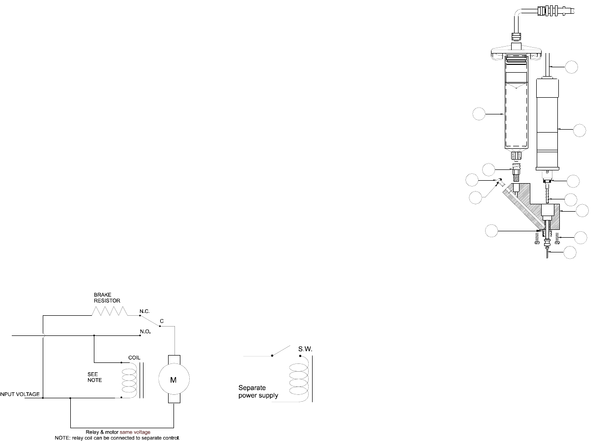
and should be shunted to positive motor stop. Below is a diagram of a
simple braking circuit:
Figure 4.0
11
9. MAINTENANCE AND CLEANING:
Figure 6.0
9.1 Valve Purging:
Refer to figure 6.0
4. Release fluid pressure.
5. Remove barrel of fluid (11) from the valve.
6. Remove dispense tip (7).
7. Install a barrel of dispensing conditioner (Part number 7305XCON)
to the valve inlet (10).
8. Set air pressure at 8.0 Psi.
9. Turn on valve and let it run until the conditioner is the only material
being dispensed at the valve outlet. If the conditioner is unable to
force the dispense fluid out the valve then proceed to the “Thorough
Cleaning” section.
10. Turn off valve and release air pressure.
MICROVALVE
TS5000
4
3
5
6
7
10
9
8
2
1
11
DO NOT REMOVE
THIS FITTING
12
10
8. TROUBLESHOOTING
PROBLEM POSSIBLE CAUSE CORRECTION
No Fluid Flow
Dispense tip is plugged Replace tip
Motor does not receive
signal
Make sure all connections are
secured
Motor running in
reverse
Reverse motor cable
connection.
Barrel of dispense fluid
is emptied
Replace with new fluid barrel.
Fluid feed pressure is
too low
Increase feed pressure.
Valve damaged
Return valve to factory for
refurbishment
Inconsistent
Fluid Flow
Fluid pressure
fluctuating
Make sure fluid pressure is
constant
Valve on time is too
short
Increased valve on time.
Excessive motor reverse
time
Reduce reverse time or turn off
completely.
Air trapped in fluid
housing
Purge valve properly
Fluid drools after the
valve turned off
Air trapped in fluid
housing
Purge valve properly
Air trapped in fluid
reservoir
Remove air from reservoir
Excessive fluid feed
pressure
Reduce pressure or turn off
pressure when the valve is
idled.
Dispense tip clogged
Tip contacting substrate Increase dispense height
Tip bent or damaged Replace tip
Particles size in fluid
too big
Replace with bigger tip
7
5.3 Air connection:
Filtered air supply must be precisely regulated and should be set between
1-20 psi. The air supply is not used as the main dispensing force. It is
only required to move the fluid to the feed screw chamber.
The valve is supplied with sample of 10 and 30-CC air power syringe
assembly. The syringe of fluid can be mounted directly onto the valve
inlet fitting. Fluid can also be supplied from a remotely located
container, such as cartridge systems.
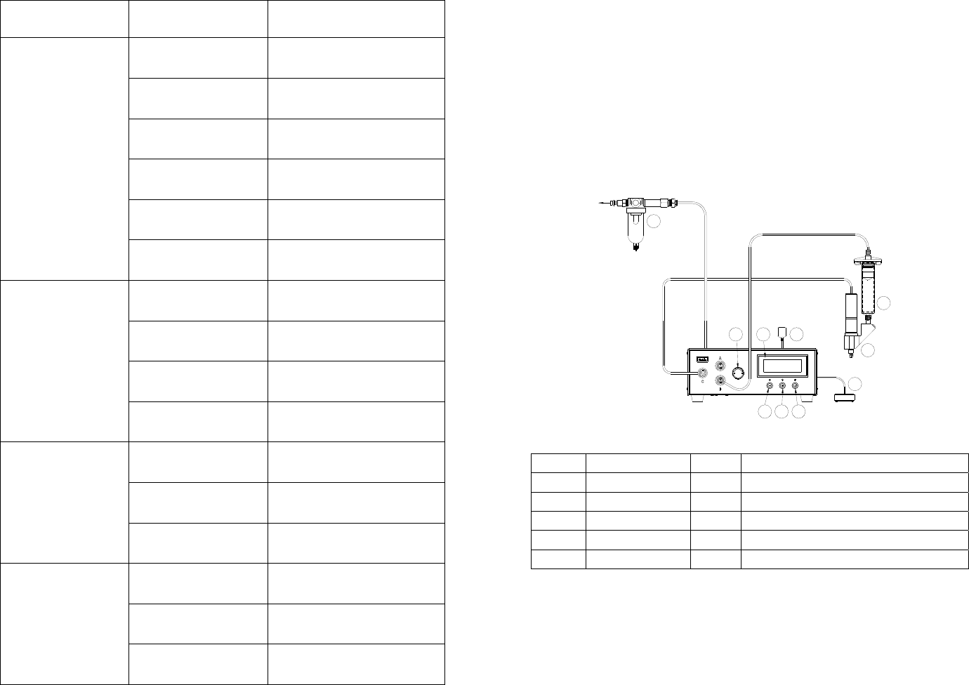
6. TYPICAL SYSTEM SETUP
Figure 5.0
Items Description Items Description
1 Power Button 6 Air pressure regulator knob
2 Mode Button 7 Foot Switch
3 Set Button 8 TS5000 Rotary Pump
4 LCD Display 9 Air Filter
5 Power Adapter 10 Material reservoir
TO AIR SOURCE
5
8
10
7
321
64
9
8
7. DISPENSING APPLICATIONS
The following details of dispensing applications are extremely important. The
dispense rate and repeatability rate of the valve can be affected by these
parameters:
A. DC Motor Voltage Level:
Voltage controls motor speed (RPM). High voltage produces high
motor speed and low voltage reduces motor speed.
B. Motor shaft Speed:
Motor gear ratio configuration determines final shaft speed. High
RPM = High Output. Low RPM = Low Output.
C. Feed screw pitch:
Rate of fluid dispensed is determined by the pitch of the feed screw.
A high pitch number will produce a low dispense rate and a low pitch
number will produce a higher dispense rate.
D. Dispense tip:
The size of the dot diameter or bead width is determined by the
dispense tip. A low gauge number (larger I.D.) will dispense a large
diameter dot or a wide bead. A high gauge number (smaller I.D.)
will dispense a smaller diameter dot or a narrower bead.
Dispense tip sizes smaller than 25-gauge and longer than 1/2" are not
recommended to use with solder paste. A normal rule of thumb to
choose the dispense tip size is that the dot size equal 1.5 times the
internal diameter of the dispense tip.
E. Fluid feed pressure:
The fluid feed pressure does affect the amount of fluid dispensed
through the valve. Optimum feed pressure is dependent upon
viscosity of fluid dispensed. Only in unusual circumstances should
the feed pressure exceed 20 psi.
F. Dispense Fluid:
The viscosity of the dispense fluid along with the particulate
additives to the dispense fluid will also determine the dispense rate.
Ability to dispense may be directly related to the fluid formulation.
G. Dispense cut off:
The best method of stopping fluid flow at the end of the cycle is to
short the motor (grounding the DC voltage signal through a current
limiting resistor). This method provides a complete rotational brake
of the motor at the shut off point. Another method of stopping fluid
flow is to reverse the motor rotation by reversing the DC voltage
signal. This can be described as suck-back action. In both cases, a
no-drip dispensing action can be achieved. Turn off the fluid feed
pressure when the valve is not dispensing will prevent dripping and
oozing.
9
H. Dispense tip height:
The distance between the dispense tip and substrate surface is
extremely important. To obtain accurate dot size, the dispense tip
height should remain constant for each dot/bead. If the dispense tip
height fluctuates during dispense process, the dot/bead size will vary.
If the dispense tip touches the dispense surface, clogging will occur.
I. Fluid (Material) condition:
The physical condition of the dispense fluid is very important to
successful dispensing. There are a number of conditions that can
prevent continuous and consistent dispensing such as:
1. Freshness: Old fluid (most fluid have a recommended shelf life)
leads to erratic dispensing and frequent clogging, especially with
solder paste. Make sure to check the fluid shelf life before starting
the dispense process.
2. Separation: Fluid with high content of solid particles, such as solder
paste, tends to separate at high pressure. If the dispense fluid
started to separate, please replace it with new fresh fluid.
3. Particles sizing: Do not attempt to dispense solder paste with
particle sizes bigger than 75 microns (-200+325 mesh size).