TS5000-user-guide.pdf - 第5页
12 Note: Solvent can be used for purging inst ead of conditioner. If a solvent if used, remember to reduce air pre ssure. Also che ck the chemical compatibilit y chart to determine if solvent used will not affect the Vit…
4
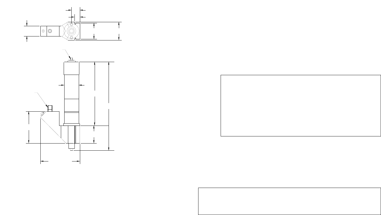
Figure 2.0 Valve with 6.0-Watt Motor
2. UNPACKING AND INSPECTION
Carefully unpack the valve and examine the items contained in the carton.
These will include:
• Valve Assembly
• Valve bracket
• Sample syringe kit
• Sample Needle Kit
• Cleaning kit
• User guide
3. DESCRIPTION
The TS5000 is a self contained fluid dispensing valve capable of depositing
shots down to 0.008” (0.200mm) in diameter at rates of 5 shots per second.
Fluid can also be accurately dispensed in continuous beads in widths from
0.008” (0.200mm) at rates up to 4” per second. In both cases, dot or bead,
accurate and repeatable dispensing can be accomplished in production by
following the instructions in this manual.
VALVE
TS5000
.90" (22.9mm)
3.94" (100.0mm)
5.48" (139.2mm)
.34" (8.6mm)
.52" (13.2mm)
.62" (15.7mm) 1.12" (28.5mm)1.00" (25.3mm)
1.97" (50.0mm)
2.45" (62.2mm)
1.09" (27.7mm)
24" (610mm) LONG CALBE
FLUID INLET
13
assembly. (Make sure not to tilt the motor during this process.) Turn
the motor off. If the motor/feed screw assembly still cannot easily be
removed, return the valve for repair.
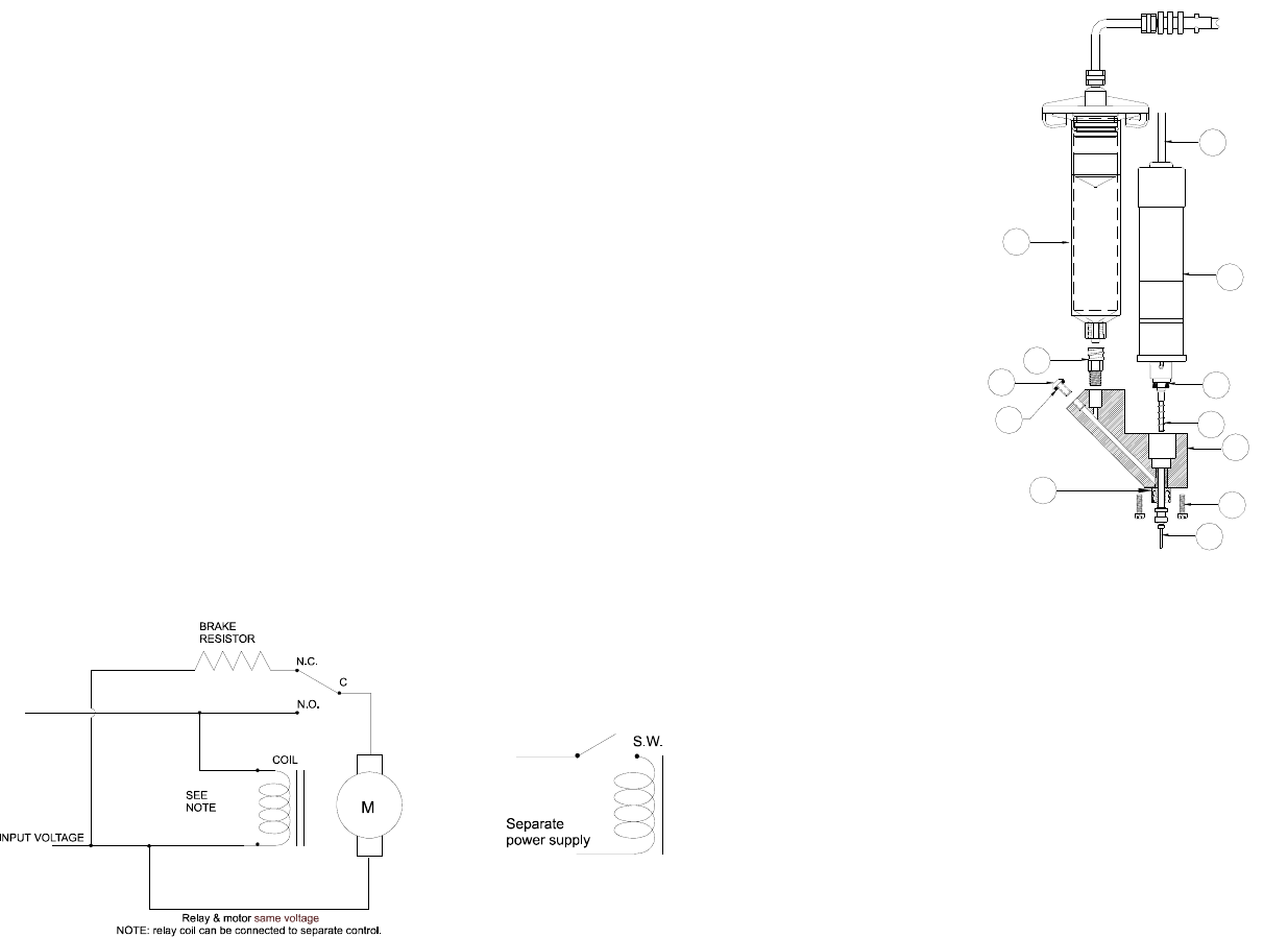
8. Disconnect the motor cable (1) from the controller.
9. The entire feed screw (4) can now be cleaned with a solvent. Use the
brush included the cleaning for this process. Rho-Chem 7642 or a
similar solvent can be used.
CAUTION:
• Do not drop, or exert any forces on the feed screw. This will cause
permanent deflection in the alignment of the feed screw to the
motor shaft
• Do not remove the feed screw from the motor shaft during cleaning.
Doing so will cause misalignment between feed screw and motor
shaft
• Do not submerge motor in solvent
10. Visually inspect the feed screw as closely as possible and make sure
the feed screw is free of all foreign material. Repeat cleaning
operation if necessary
11. Remove the clean out screw (9) and O-ring (8) from valve body (5)
CAUTION: Do not remove the male luer lock fitting and locking hub (12) from the
valve body (5). This is a precisely aligned part. Removal of this part will damage
the valve permanently.
12. Using the brush provided, clean the feed screw chamber with solvent.
13. Using a micrometer to measure the major diameter of the feed screw
threads. If the diameter is measure less than 0.1240”, return the valve
for feed screw replacement.
14. Replace the O-ring (3) on the feed screw (Part number TSD1400-
010B)
15. Using the brush provided, clean the valve body with solvent.
16. Use dry air pressure to blow out passageways.
12
Note: Solvent can be used for purging instead of conditioner. If a solvent if
used, remember to reduce air pressure. Also check the chemical compatibility
chart to determine if solvent used will not affect the Viton O-ring on the feed
screw.
9.2 Thorough Cleaning:
A more through cleaning procedure should be done whenever the following
occur:
• Dispense fluid is changed to different type.
• Dispense fluid started to cure in the valve
• Valve has been dispensing for one month.
• Dispense tip clogged frequently.
Tool required: Open-end wrench, 3/32 hex wrench (included in valve cleaning
kit, part number: 5000-000-013)
1. Follow steps 1-7 in “Valve Purging” section.
2. Remove barrel of conditioner (11) from the valve assembly.
3. Disconnect the motor cable (1) from the controller.
4. Using a 3/32 hex wrench to unscrew the two socket head screws (6)
from the valve assembly.
5. Grasp the motor assembly (2) as close to the valve body (5) as
possible. (Pulling on the motor assembly near the cable and may
result in separation on the motor from the gear head.) Gently pull
straight up on the motor assembly. The motor/feed screw assembly
should pull out of the valve body. Do not pry on the motor if the
motor assembly does not withdraw easily. If the motor/feed screw
assembly has been removed from the valve, go to step 10, otherwise
continue to step 7.
6. Reattach control cable (1) to the controller, taking care to properly
attach with correct polarity. (Feed screw should rotate
counterclockwise when viewed from the dispense tip.)
7. Grasp the motor near the valve body to keep the motor from rotating.
With the motor running, pull straight up on the motor/feed screw
5
The amount of fluid dispensed will be determined by the following parameter:
• DV Voltage input
• Motor assembly selections
• Feed screw pitch
4. THEORY OF OPERATION
The TS5000 Rotary Microvalve dispenses fluid with a positive displacement
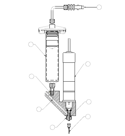
action using a rotary feed screw principle. Fluid in held in a feed reservoir (1)
under a positive head of air, between 1 to 20 psi, depending upon the viscosity
of the fluid. This positive air pressure, supplied by the air line (7), forces the
fluid out of the barrel (1) into the vertical feed shaft of the valve body (2), and
then through the angled feed shaft (3), to the feed screw chamber (4). Fluid
flows from this point (4) to the dispense point (5) is controlled by the feed
screw rotation in the feed direction. The feed screw is driven by the DC motor
(6). Applying a DC voltage signal to the DC motor (6), will rotate the feed
screw and the fluid will be forced out the dispense tip. The actual fluid
deposited is dependent upon adhesion of the dispensed fluid to the substrate.
Shearing of the fluid is achieved by reverse Z-motion (tip retraction). When
the motor stops, the unit remains in position for a fraction of a second (dwell)
to allow the last drop of fluid to flow out of the dispense tip. After the dwell
period, the automation equipment moves the TS5000 valve to the next position.
Figure 3.0
MICROVALVE
TS5000
7
6
4
8
3
2
1
5
Motor Assembly
Dispense Tip
Fluid Reservoir
Vertical Feed
Shaft
45° Feed Shaft
Locking Hub
Feed Screw
Chamber
Reservoir
Air Line
6
5. SETUP INSTRUCTIONS
5.1 Mechanical Mounting:
Normally, the TS5000 valve is used on an automated XYZ table with full
motion control in the three planes. It is very important that the valve be
mounted on the Z-axis gantry in a secure manner that will not allow
loosening during dispense operation. The Z-axis must move in a precise
and repeatable motion for successful dispensing.
The provided mounting bracket, or customer supplied bracket, must be
attached to the Z-axis in a manner that will provide the valve
perpendicular travel to the horizontal plane of the surface on which the
fluid will be dispensed. The mounting should provide a means of
accurately adjusting the gap between the dispense tip and the substrate
surface such as a touchdown sensing device or a fixed distance standoff.
5.2 Electrical Connection:
The TS5000 valve requires an electrical connection of two wires for the
DC motor. The motor lead wires are 24” long. The black lead wire
should be connected to the negative or neutral lead from the motor
control voltage source. To verify the connection, check the rotation
direction of the feed screw. When correctly connected, a positive voltage
signal will drive the feed screw in a counter clockwise direction when
view from the dispense tip end.
The recommended controller for the TS5000 valve is the TS500R. If
another controller is used made sure the control voltage signal is
precisely control. The signal should be from a regulated power supply
and should be shunted to positive motor stop. Below is a diagram of a
simple braking circuit:
Figure 4.0
11
9. MAINTENANCE AND CLEANING:
Figure 6.0
9.1 Valve Purging:
Refer to figure 6.0
4. Release fluid pressure.
5. Remove barrel of fluid (11) from the valve.
6. Remove dispense tip (7).
7. Install a barrel of dispensing conditioner (Part number 7305XCON)
to the valve inlet (10).
8. Set air pressure at 8.0 Psi.
9. Turn on valve and let it run until the conditioner is the only material
being dispensed at the valve outlet. If the conditioner is unable to
force the dispense fluid out the valve then proceed to the “Thorough
Cleaning” section.
10. Turn off valve and release air pressure.
MICROVALVE
TS5000
4
3
5
6
7
10
9
8
2
1
11
DO NOT REMOVE
THIS FITTING
12