06_SM481_Service_Manual Flow Manual.pdf - 第6页
在线预览 06_SM481_Service_Manual Flow Manual.pdf PDF 文档。

Table of Contents
6-1
Table of Contents
Main Contents
Table of Contents ................................................................................................ 6-1
Main Contents ................................................................................................ 6-1
Chapter 6. PCB Flow ............................................................................................... 6-3
6.1. PCB Flow ............................................................................................... 6-3
6.1.1. Required Tools ........................................................................................ 6-3
6.1.2. Procedure to change the PCB flow on conveyor ..................................... 6-3

PCB Flow
6-3
Chapter 6. PCB Flow
6.1. PCB Flow
6.1.1. Required Tools
+ and – shape tipped screw driver set
L-wrench set
Nipper and cable tie
6.1.2. Procedure to change the PCB flow on conveyor
1. Manipulate the teaching box to move the X-Frame to the rear side.
2. Turn Off the PC in normal way. Then turn off the main switch on the front side of the machine.
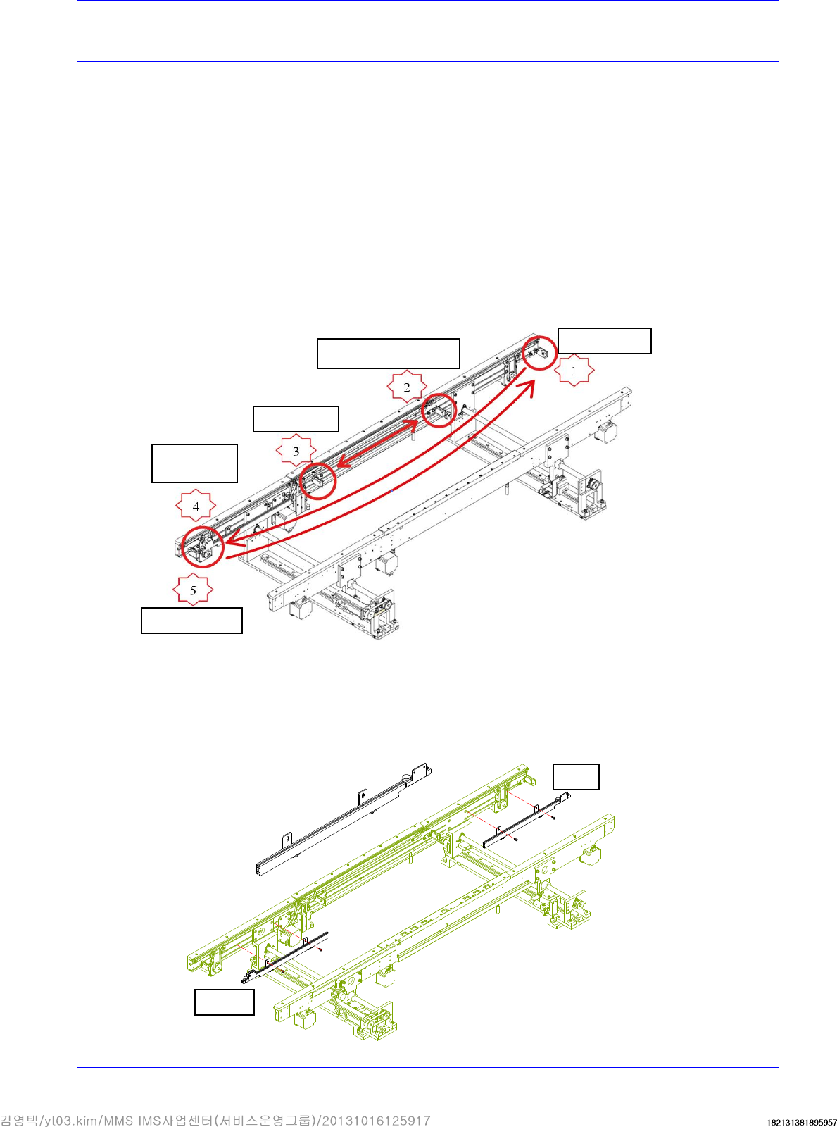
3. Refers to the sensor to be moved when changing the PCB flow.
4. Disassemble, move and assemble the sensor rail in order as shown in the following figure.
① Unscrew the fixing bolts securing all sensors and sensor brackets and remove them.
② Unscrew the fixing bolts securing the sensor rail and move it to the right. Then assemble
it again.
Quick Load
Sensor
Place Sensor
Input Sensor
Output Sensor
Wait Sensor Bracket
Before
After