06_SM481_Service_Manual Flow Manual.pdf - 第8页
Advance d High Speed Flex i ble Mounter 6-4 ③ A ss em ble t he W ait s enso r a nd P laceme nt sensor by ch a ngi ng thei r position. ④ A ss em ble t he Entry sen s or a nd Exit sen s or by ch angi ng thei r position. ⑤ …
PCB Flow
6-3
Chapter 6. PCB Flow
6.1. PCB Flow
6.1.1. Required Tools
+ and – shape tipped screw driver set
L-wrench set
Nipper and cable tie
6.1.2. Procedure to change the PCB flow on conveyor
1. Manipulate the teaching box to move the X-Frame to the rear side.
2. Turn Off the PC in normal way. Then turn off the main switch on the front side of the machine.
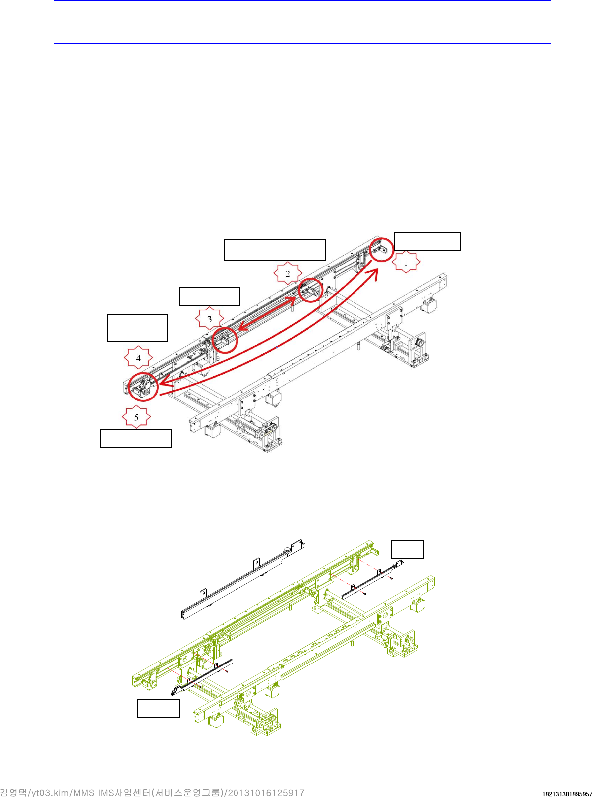
3. Refers to the sensor to be moved when changing the PCB flow.
4. Disassemble, move and assemble the sensor rail in order as shown in the following figure.
① Unscrew the fixing bolts securing all sensors and sensor brackets and remove them.
② Unscrew the fixing bolts securing the sensor rail and move it to the right. Then assemble
it again.
Quick Load
Sensor
Place Sensor
Input Sensor
Output Sensor
Wait Sensor Bracket
Before
After
Advanced High Speed Flexible Mounter
6-4
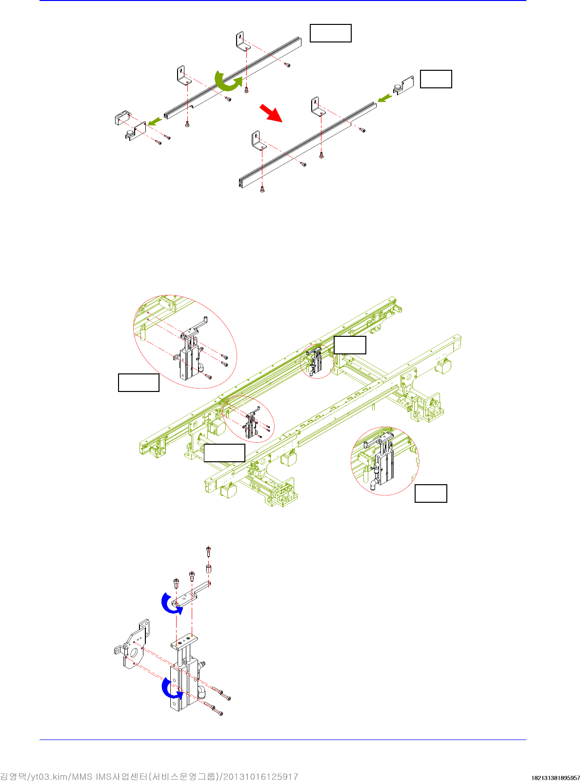
③ Assemble the Wait sensor and Placement sensor by changing their position.
④ Assemble the Entry sensor and Exit sensor by changing their position.
⑤ Unscrew the fixing bolts securing the placement stopper and remove it.
⑥ Remove the stopper cylinder and cylinder bracket. Then assemble them by rotating them
by 180°.
Before
After
Before
After
Before
After
PCB Flow
6-5
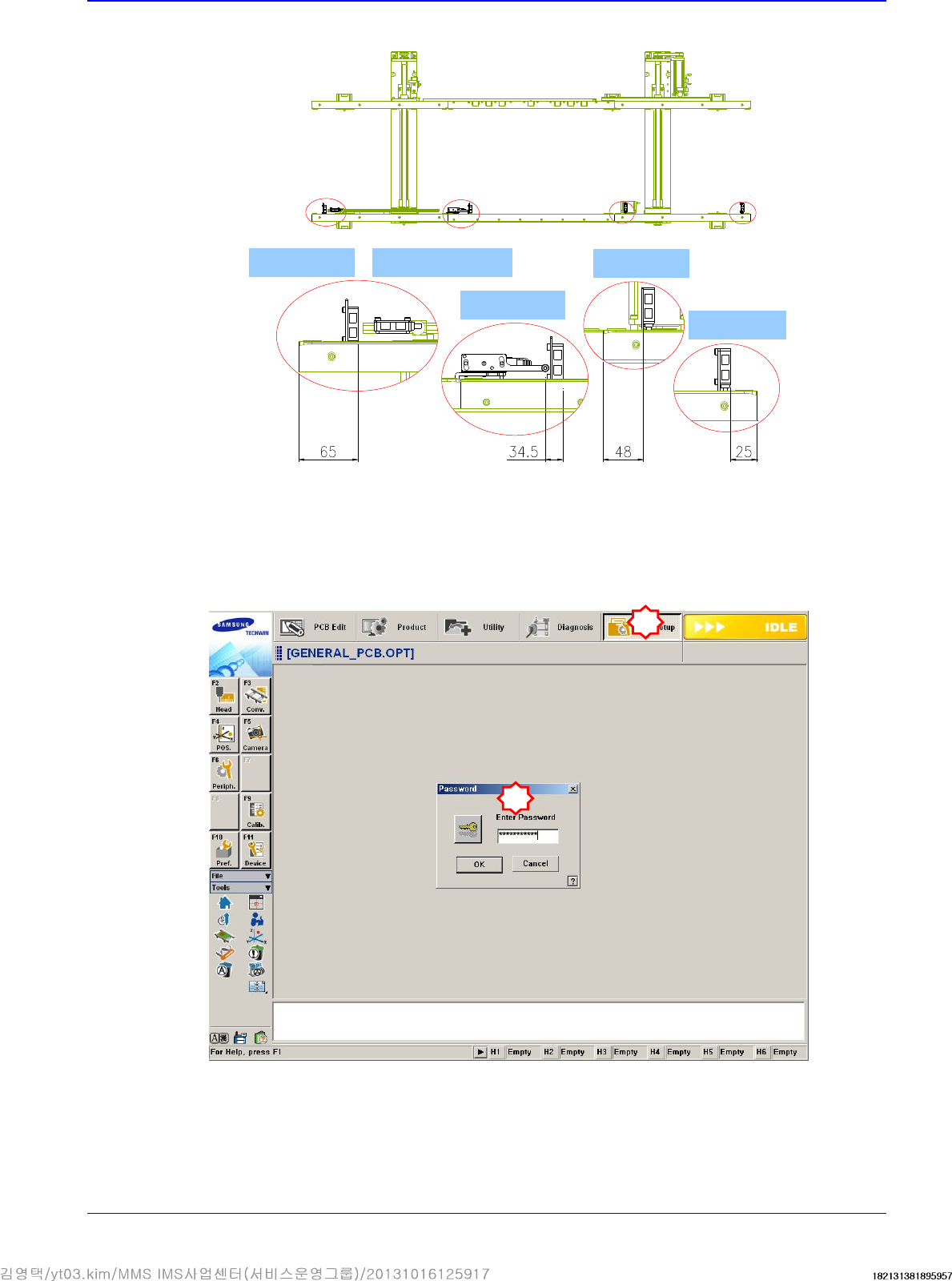
5. After moving them all, check whether they are as follows:
6. Select the secondary Option menu from the System Setup Factory menu and select the PCB
flow to be changed from the ‘Factory Setting Option’ dialog box.
In order to access the Factor menu, a separate password must be input in the System Setup
Menu.
Quick load sensor
Wait sensor
Place sensor
Entry sensor
Outpu sensor
1
2