XPM2-Site_Preparation.pdf - 第16页
Site Preparation & Installation Section: 2 Page: 16 Revision Date: April 2005 Grounding A dedicated equipment ground from the facility distributio n pan el for the oven is required to comply with Article 250 of the N…
Site Preparation & Installation Section: 2 Page: 15 Revision Date: April 2005
Electrical Power
Vitronics Soltec electrical wiring design is based on the USA National Electrical Code
(NFPA-70 & 79) from the National Fire Protection Association guidelines and European
Standard EN 60204-1. Vitronics Soltec makes no claims or warranties for compliance to
any other standard or any local, state, federal or country codes, expressed or implied.
Unless purchased as an option, XPM
2
ovens are not equipped with a main circuit
breaker disconnect switch. A properly rated fused disconnect or main circuit breaker
switch, facility power cable and connection to the oven switch must be supplied by the
customer and installed by a qualified electrician in accordance with applicable regulations
and codes.
Estimating Power Requirements
Refer to the Electrical Configuration on the Purchase Order for the oven or the oven’s Nameplate Data to
determine the voltage. CAUTION: Incorrect voltage can result in extensive damage to the oven .
The Electrical values in the data tables are based on Vitronics Standard Factory Settings for power
management. Modification to the power management settings in the Oven Control Software may
render these numbers invalid
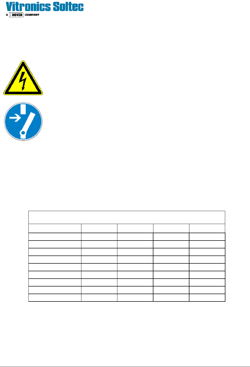
XPM
2
Current Draw at Start-up in Amperes (kVA)
MODEL
520 730 / 820 940 / 1030 1240
200 vac, 3 ph 110 (38) 120 (42) 120 (42) 120 (42)
208 vac, 3 ph 120 (43) 120 (43) 120 (43) 120 (45)
220 vac, 3 ph 120 (46) 125 (48) 125 (48) 130 (50)
240 vac, 3 ph 125 (52) 130 (54) 135 (56) 140 (58)
380 vac, 3 ph 55 (36) 60 (39) 60 (39) 65 (43)
400 vac, 3 ph 60 (42) 65 (45) 65 (45) 65 (45)
415 vac, 3 ph 60 (43) 65 (47) 65 (47) 70 (50)
440 vac, 3 ph 60 (46) 65 (50) 65 (50) 70 (53)
480 vac, 3 ph 65 (54) 70 (58) 70 (58) 70 (58)
Power Connections
Connect the power and ground cables from the dedicated service (fused disconnect or circuit breaker) to the
power connectors located inside equipment access door located at the front-right corner of the oven. Connect
and secure the cables to the power and ground blocks. A hex wrench for socket head screws will be needed
to tighten the power connections after inserting the supply conductors. The Circuit Breaker also uses socket
head screws for securing the conductors.

Site Preparation & Installation Section: 2 Page: 16 Revision Date: April 2005
Grounding
A dedicated equipment ground from the facility distribution panel for the oven is required to comply with Article
250 of the National Electrical Code. The equipment ground is necessary for the safety of personnel as well
for safe and reliable oven operation. All grounding and service wiring should be installed and tested by a
qualified licensed electrician.
Power Quality
• The oven control systems do not condition the facility supplied power to the oven .
• For proper operation, the power must be maintained at a "cleanliness level" of less than 10% of High
frequency (200V rise / microsecond) noise on the input voltage.
• The AC voltage supplied to the oven must be + 10% of the stated voltage. (For example 220 VAC must
be between 198VAC and 242 VAC).
• The voltage frequency must be within + 1% limit of the stated frequency.
• For 3 Phase power, any line to neutral voltage must be within + 5% of the arithmetic mean of the three line
to neutral voltages.
Any and all damage, service and costs resulting from poorly conditioned facility power is solely the
responsibility of the customer.
Power Distribution
A dedicated facility electrical distribution panel is recommended. Avoid powering heavy duty, electrically noisy
equipment from the same panel as the oven; such as:
• Heavy air conditioners
• Elevators
• Heaters
• Office equipment
• Fluorescent lights
• Air ionizers
• High current motors such as electric drills or water pumps
• Welders
• Placement equipment
Electromagnetic Fields
As with all electronically controlled equipment, the oven should be installed in an area not affected by
electromagnetic fields generated by other pieces of equipment.
Uninterruptable Power Supply Systems
Vitronics Soltec offers as and option, a UPS system for the oven which operates the oven conveyor, computer
/ control system and hood lifts for approximately five minutes after loss of facilities operating power. Consult
the purchase order for configuration. It is important to note that neither UPS option will operate the oven
heaters or cell fans.
Site Preparation & Installation Section: 2 Page: 17 Revision Date: April 2005
Nitrogen Supply (optional)
Oven Model 520 730 / 820 940 / 1030 1240
N
2
Process volume [low] CFH (M
3
/hr) 400 (12) 600 (17) 800 (23) 1000 (28)
N
2
Process volume [high] CFH (M
3
/hr) 1400 (40) 1600 (45) 1800 (51) 2000 (57)
N
2
volume [w/quick atmosphere purge] 2500 CFH (71 M
3
/hr)
Pressure regulated to 50-70 PSI (3.5-4.8 Bar)
Fitting size 3/8" Female National Pipe Thread (FNPT)
Supply pipe size 1/2"
Nitrogen purity [typical] * 99.9995%
Moisture content < 1 Volume Parts per Million (VPPM) @ 70
o
C
Oxygen content [typical] * < 5 Parts per Million (PPM)
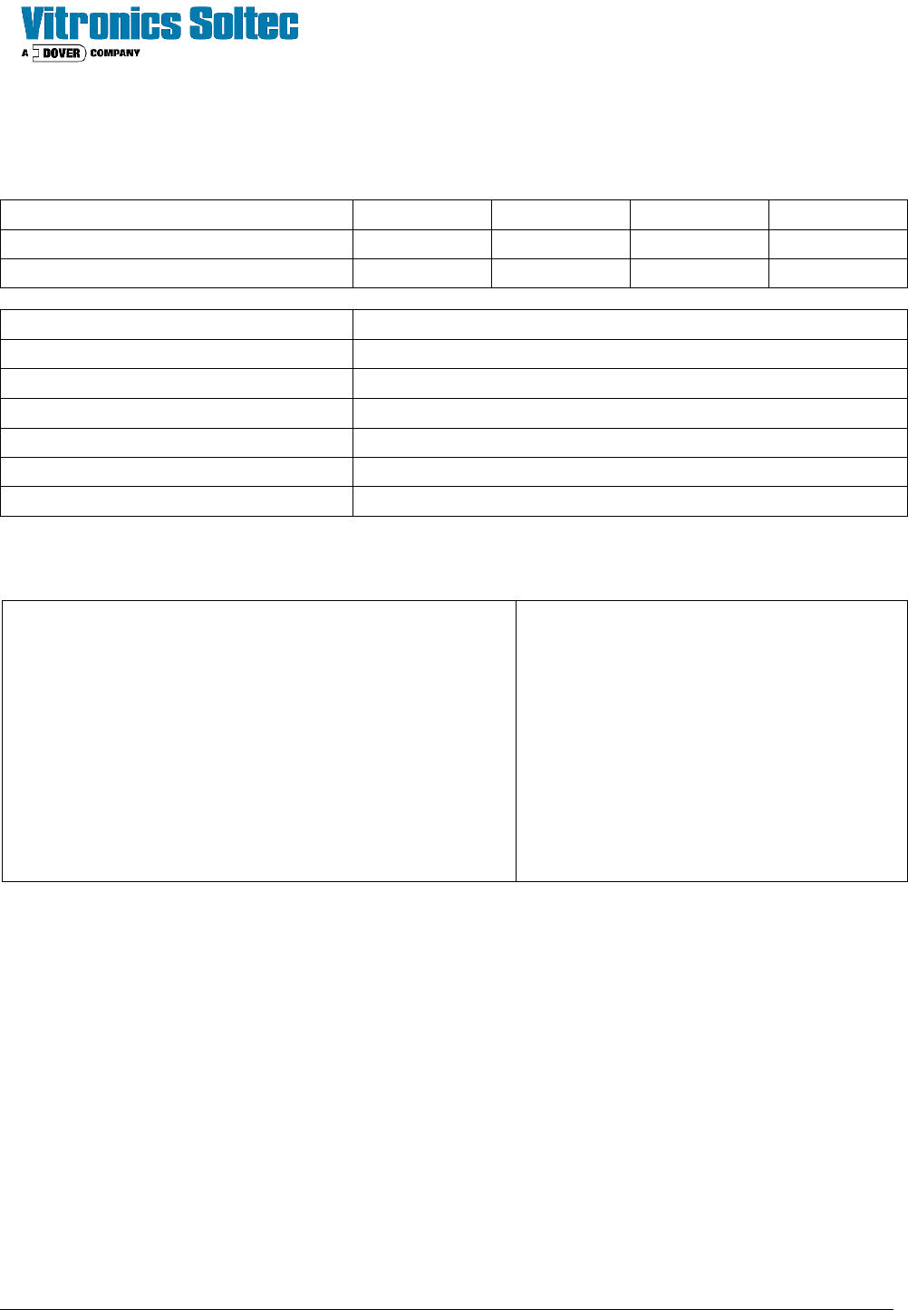
* Multiple grades of Nitrogen are available. The following table is provided for reference to the incoming
Nitrogen supply.
%N2 Purity N
2
PPM O
2
PPM
99.0000% 990000 10000
99.5000% 995000 5000
99.9000% 999000 1000
99.9500% 999500 500
99.9900% 999900 100
99.9950% 999950 50
99.9990% 999990 10
99.9995% 999995 5
The actual atmosphere within the tunnel will vary depending
on oven configuration and process parameters.
Typical atmosphere performance will yield O
2
levels greater
than the source N
2
purity.
99.9999% 999999 1
The oven is equipped with a pressure regulator and gauge for control of the nitrogen supply.