00191663.pdf - 第18页
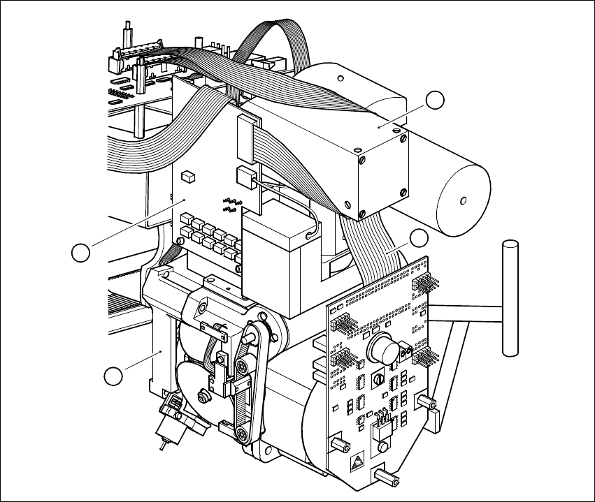
DCA Option Retrofit Instructions 80F5 05/99 issue 18 1 Fig. 1 - 1 DCA camera system Key to Fig. 1 - 1 (1) FC c amera 16 x 16 (2) Ill umina tion cont rol b oard (3) 6- nozzle revo lver head (4) Rib bon ca ble for th e sta…

Retrofit Instructions 80F5 DCA Option
05/99 issue 1 Overview
17
1Overview
These instructions describe how to retrofit the DCA option for SIPLACE 80F5 placement sys-
tems. 1
To retrofit the DCA option, the 6-nozzle revolver head of the 80F5 placement system must be
equipped with a new component camera system. The vision analysis unit in the control unit is also
replaced with a unit that also incorporates the DCA option. 1
The DCA component camera system essentially consists of the following components: 1
– New camera housing (item 1 in Fig. 1 - 1)
– New CCD camera with 4 illumination planes
– New illumination board for the illumination control (item 2 in Fig. 1 - 1)
– New ribbon cable for the star motor (item 4 in Fig. 1 - 1)
– New cover for the 6-nozzle revolver head with FC camera
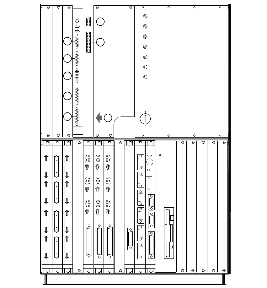
– MVS 340 vision analysis unit, DCA option (item 1 in Fig. 1 - 2)
This will enable the 6-nozzle revolver head to insert 1
– flip-chips and
– bare dies
on the 80F5 placement system, in addition to standard components. 1
PLEASE NOTE: 1
The camera system and illumination control form a single unit and must always be replaced to-
gether during servicing. 1
DCA Option Retrofit Instructions 80F5
05/99 issue
18
1
Fig. 1 - 1 DCA camera system
Key to Fig. 1 - 1
(1) FC camera 16 x 16
(2) Illumination control board
(3) 6-nozzle revolver head
(4) Ribbon cable for the star motor
1
2
3
4
Retrofit Instructions 80F5 DCA Option
05/99 issue 1 Overview
19
1
Fig. 1 - 2 MVS 340 analysis unit in the control unit
(1) Vision system, PCB and component analysis unit
(2) COM2
(3) COM1
(4) HS3L communications connector
(5) Monitor connector (SVGA)
(6) Trigger / Flash connector
(7) Camera connectors: (1) PCB camera (3) Cmpt. camera, 6-nozzle revolver head
(8) Camera connectors: (2) P&P head camera (4) FC camera, Pick&Place head
+24V
-15V
+15V
-12V
+12V
Achsservice
Servo
Aus
Servo
Aus
Servo
Aus
Servo
Aus
Servo
Aus
Servo
Aus
AUI
Servo
Aus
Servo
Aus
Servo
Aus
Kamera
Kamera
2/4
1/3
AUX
Batterie
3,8V
GND
S-COM
S-COM
Reset
Abort
+5V
DISPLAY
HS3L
2
1
MVS
ICOS
X5se
X5sg
X4se X3se
X4sg X3sg
X3tq
X3sn
X3sm
X2sp
X2se
X2sg
2
3
8
7
6
5
4
1
X2sfX3sfX4sfX5sf
Achsservice
Achsservice
Harddisk
X7sa X6sa X5sa
X4sa
S-COM 2LPT S-COM 1
VGA
Tast
Reset
Floppy
S-COM 1 S-COM 2 S-COM 3 S-COM 4 CAN-Bus CAN-Bus
X2sd X3sd X4sd X5sd X6sd X7sd
X3