00191663.pdf - 第20页
DCA Option Retrofit Instructions 80F5 05/99 issue 20 (9) Battery (10) Power s upply uni t 2 T echnical dat a for the component vision system for flip-ch ip s, bare dies and st andard component s on the 6-nozzl e revolve …
Retrofit Instructions 80F5 DCA Option
05/99 issue 1 Overview
19
1
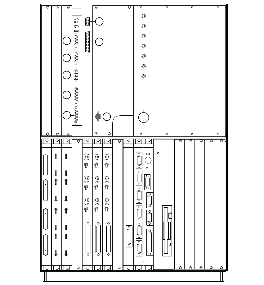
Fig. 1 - 2 MVS 340 analysis unit in the control unit
(1) Vision system, PCB and component analysis unit
(2) COM2
(3) COM1
(4) HS3L communications connector
(5) Monitor connector (SVGA)
(6) Trigger / Flash connector
(7) Camera connectors: (1) PCB camera (3) Cmpt. camera, 6-nozzle revolver head
(8) Camera connectors: (2) P&P head camera (4) FC camera, Pick&Place head
+24V
-15V
+15V
-12V
+12V
Achsservice
Servo
Aus
Servo
Aus
Servo
Aus
Servo
Aus
Servo
Aus
Servo
Aus
AUI
Servo
Aus
Servo
Aus
Servo
Aus
Kamera
Kamera
2/4
1/3
AUX
Batterie
3,8V
GND
S-COM
S-COM
Reset
Abort
+5V
DISPLAY
HS3L
2
1
MVS
ICOS
X5se
X5sg
X4se X3se
X4sg X3sg
X3tq
X3sn
X3sm
X2sp
X2se
X2sg
2
3
8
7
6
5
4
1
X2sfX3sfX4sfX5sf
Achsservice
Achsservice
Harddisk
X7sa X6sa X5sa
X4sa
S-COM 2LPT S-COM 1
VGA
Tast
Reset
Floppy
S-COM 1 S-COM 2 S-COM 3 S-COM 4 CAN-Bus CAN-Bus
X2sd X3sd X4sd X5sd X6sd X7sd
X3

DCA Option Retrofit Instructions 80F5
05/99 issue
20
(9) Battery
(10) Power supply unit
2 Technical data for the component vision system
for flip-chips, bare dies and standard components
on the 6-nozzle revolver head (DCA option)
Camera type: SONY XC75CE 2
Number of pixels: 570 x 570 2
Field of vision: 15.7mm x 15.7 mm 2
Illumination method: Front lighting (red light), 4 LED planes (even, flat,
medium, steep) 2
Image processing: HALE grey scale method (H
igh Accuracy Lead Extraction) 2
Monitor: RGB (VGA mode) 640 x 484 pixels 2
Component size: 0.25 mm x 0.5 mm ... 13 mm x 13 mm 2
Range of components
that can be detected: Flip-chips, bare dies, components up to 13mm x 13mm 2
Minimum lead spacing 0.2 mm 2
Minimum ball diameter: 110
µm 2
System sensor type (SST) 14 2
3 Line and station computer requirements
Line computer software ≥ 5.01
Station computer software
≥ 4.05
MC software
≥ 4.05
CAN firmware 2.2
SITEST
≥ 4.05
Nozzle types 750 - 759 3
Retrofit Instructions 80F5 DCA Option
05/99 issue 4 Safety instructions
21
4 Safety instructions
WARNING
This retrofit must be carried out by SIEMENS engineers. 4
È Always follow the accident prevention regulations applicable in your country, e.g. EN 60204.
È End all operations on the placement system.
È Shut down the Windows NT operating system correctly, otherwise you may experience prob-
lems when restarting the placement system or you could loose data.
È Switch the placement system off at the main switch.
È Disconnect the placement system from the power supply.
È Secure the placement system to prevent reclosing and put up a sign to indicate that servicing
work is in progress (see chapter 2 Operational Safety of the User Manual).
È Open the protective covers and move the main gantry into a comfortable working position.
WARNING
To avoid damaging the revolver head, ALWAYS observe the following points when moving the
gantry: 4
– NEVER move the gantry by pushing with your hands against the revolver head.
– NEVER move the gantry by pushing against or pulling the recessed grip of the revolver head.
The revolver head may lose its settings or be damaged on account of the high braking force of
the y gantry drive.
– NEVER push the gantry while the z axis is lowered.
– Take hold of the cast iron part of the x axis and then move the gantry.