00198274-02_DC_SIPLACE_TX-Series_DE+EN.pdf - 第129页
Size DIN A2 electric_schematic_TX Replaced by Fluid V acuum_tooling Replaced by TXmicron > Optional W eitergabe sowie V ervielfältigung dieser Unterlage, Verwertung und Mitteilung des Inhalts nicht gestattet, soweit n…
Size DIN A2
electric_schematic_TX
Replaced by
Vacuum_tooling
Replaced by
TXmicron > Optional
Weitergabe sowie Vervielfältigung dieser Unterlage, Verwertung und
Mitteilung des Inhalts nicht gestattet, soweit nicht ausdrücklich zugestanden.
Proprietary Data, company confidential.
All rights reserved
Copying of this document, giving it to others and the use or
communication of the contents thereof, are forbidden without express authority.
Doc. No.
GmbH & Co KG
ASM
Assembly Systems
Copyright reserved
0 1 2 3 4 5 6 7 8 9
Privileged business information.
Do not release
Offenders are liable to payment of damages. All rights are reserved in the
event of the grant or the registration of a utility model or design.
Zuwiederhandlungen verpflichten zu Schadenersatz. Alle Rechte ins-
besondere für den Fall der Patenterteilung oder GM-Eintragung vorbehalten.
03149194-030101LE3
Function
Page ==VT=TXm+03149194_0301/123
Sheet
123
/
2
03149194-030101LE3
drawing number:
Ed.
Original
Pingist
Date
Date
Modification
Appr
09.03.2017
Name
-X1.VS2
-X1.VS2
-
X1.VS2
-X1.VS2
1 2 3 4
Cable fixing
on Vacuum-tube
Cable fixing
on Vacuum-tube
Cable fixing
on Vacuum-tube
Cable fixing
on Vacuum-tube
1 2 3 4
VAC
Place-area 2
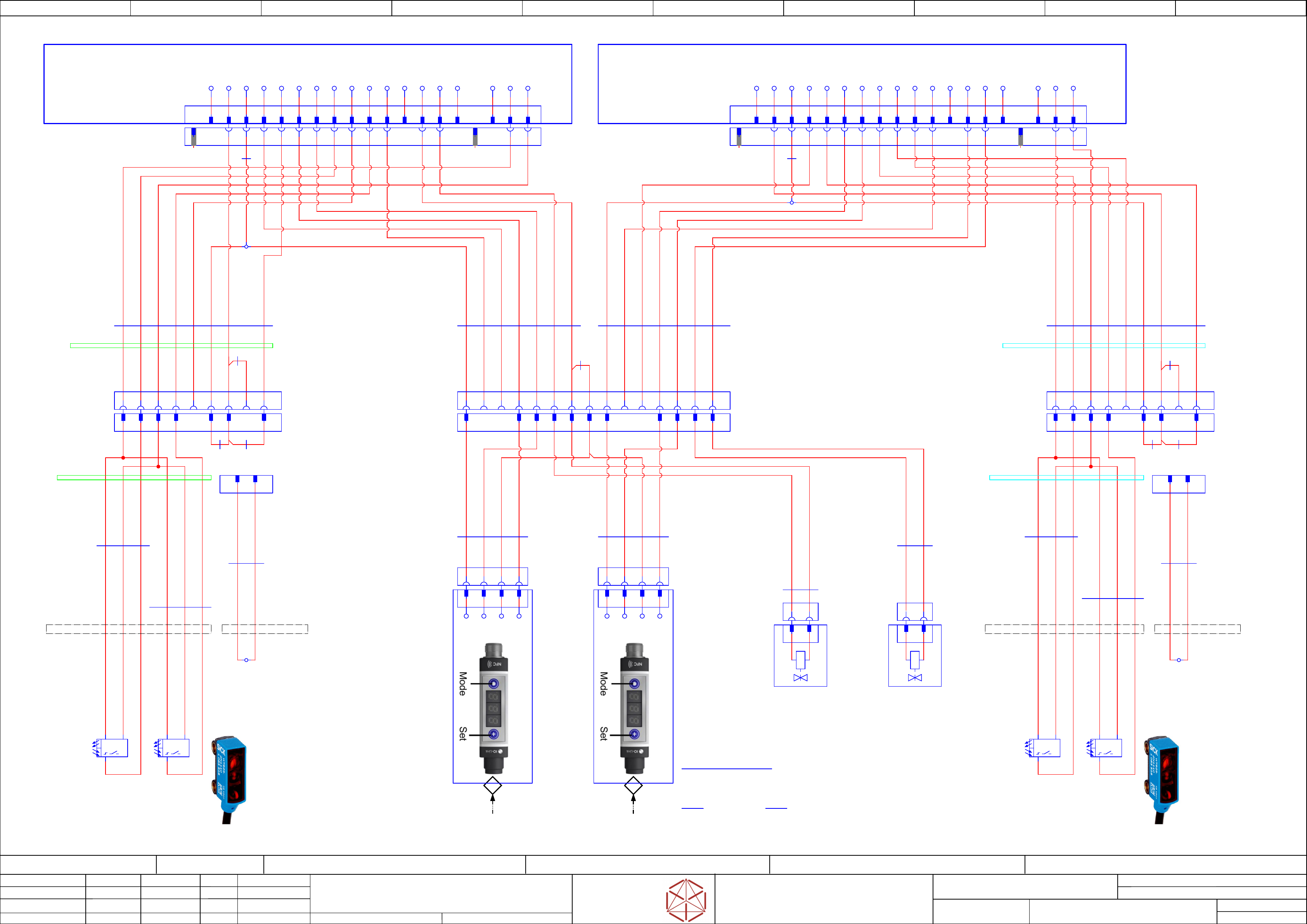
For detailed instructions on how to program the Schmalz vacuum sensor,
see the Manuel VSi Series: 03118829- Operating-Instructions
See point 6.2 and 6.3 in the manual. The recommended settings are:
OUT 1:
OUT 1:
OUT 1:
OUT 1:
Programming vacuum sensor:
Programming vacuum sensor:
Programming vacuum sensor:
Programming vacuum sensor:
SP1 -> 450 mbar
rP1 -> 300 mbar
EF -> OUT 1 -> H.no
P-n -> PnP
VAC
Place-area 1
SP2 -> 150 mbar
rP2 -> 100 mbar
EF -> OUT 2 -> H.nc
OUT 2:
OUT 2:
OUT 2:
OUT 2:
green marking
green marking blue marking
blue marking
-X1.VS1
-X1.VS1
-X1.VS1
-X1.VS1
1 2 3 4
-X34
-X34
-
X34
-X34
Options Placement area
2 3 4 6 17
GND
IN25
-A1
-
A1
-
A1
-A1
PCB: "Lane-1"
TSP-420-xx
Power-unit TSP-420-M (main-board)
03087642-
GND
5 7
+24V
700 mm
4x0,25
Connecting cable NEBU-M8W4-K-2.5-LE4
03139109
03139109
03139109
03139109 -02
-02
-02
-02
-W82.2
-
W82.2
-
W82.2
-W82.2
WHBN BU BK
8 9 10 11 12 13 14 15 16 18 19 201
IN26
IN27
IN19
IN20
IN21
IN22
IN23
IN24
+24V
+24V
GND
OU15
OU16
OU17
GND
IN25
-A2
-
A2
-
A2
-A2
PCB: "Lane-2"
TSP-420-xx
Power-unit TSP-420-M (main-board)
03087642-
GND
+24V
IN26
IN27
IN19
IN20
IN21
IN22
IN23
IN24
+24V
+24V
GND
OU15
OU16
OU17
-X34
-X34
-
X34
-X34
Options Placement area
2 3 4 6 175 7 8 9 10 11 12 13 14 15 16 18 19 201
-X34.A1
-
X34
.A1
-X34.A1
-X34.A1
AMPMODU Locking Clip Socket 2x10-pin
3 4 5 7 82 14 15 16 18
-X34.A2
-X34
.A2
-X34.A2
-X34.A2
AMPMODU Locking Clip Socket 2x10-pin
3 4 5 7 82 14 15 16 1813
-X34.VT
-
X34
.VT
-X34.VT
-X34.VT
Mini MATE-N-LOK Socket 15-pin
5
IN20(A1)
7
GND
6
OUT15(A1)
11
+24V
12
IN19(A2)
3
+24V
4
IN19(A1)
13
IN20(A2)
14
OUT15(A2)
13
-X34.VT
-X34
.VT
-X34.VT
-X34.VT
Mini MATE-N-LOK Plug 15-pin
4 6 12
-X1
3 1
-X1.Y1
-X1.Y1
-
X1.Y1
-X1.Y1
3 1
-Y1
-
Y1
-
Y1
-Y1
Vacuum generator
V
acuum generator
Vacuum generator
Vacuum generator
Vacuum_tooling_L1
Vacuum_tool
ing_L1
Vacuum_tooling_L1
Vacuum_tooling_L1
FESTO
VN-20-H-T6-PQ4-VQ5-RO2-M
03136878
-X1
3 1
-X1.Y2
-X1.Y2
-
X1.Y2
-X1.Y2
3 1
11
8
GND
15
GND
8
400 mm
2x0,25
Connecting cable NEBV-H1G2-P1-LE2
03139109
03139109
03139109
03139109 -02
-02
-02
-02
-W82.3
-W82.3
-
W82.3
-W82.3
BKRD
-Y2
-
Y2
-
Y2
-Y2
Vacuum generator
V
acuum generator
Vacuum generator
Vacuum generator
Vacuum_tooling_L2
Vacuum_tool
ing_L2
Vacuum_tooling_L2
Vacuum_tooling_L2
FESTO
VN-20-H-T6-PQ4-VQ5-RO2-M
03136878
1
+24V_VS1
9
24V_VS2
2000 mm
7x0,34
UNITRONIC® LiYY A
03139108
03139108
03139108
03139108 -05
-05
-05
-05
-W81.1
-
W81.1
-
W81.1
-W81.1
WHBN YE GY PK BU
2000 mm
7x0,34
UNITRONIC® LiYY A
03139108
03139108
03139108
03139108 -05
-05
-05
-05
-W81.2
-
W81.2
-
W81.2
-W81.2
WHBN YE GY PK BU
1 14 1593
400 mm
2x0,25
Connecting cable NEBV-H1G2-P1-LE2
03139109
03139109
03139109
03139109 -02
-02
-02
-02
-W82.4
-
W82.4
-
W82.4
-W82.4
BKRD
WH
700 mm
4x0,25
Connecting cable NEBU-M8W4-K-2.5-LE4
03139109
03139109
03139109
03139109 -02
-02
-02
-02
-W82.1
-
W82.1
-
W82.1
-W82.1
WHBN BU
135
6 619 20 19 20
-B1.2
-B1.2
-B1.2
-B1.2
IN23
+ -
900 mm
3x0,25
UNITRONIC® LiYY
03149630
03149630
03149630
03149630 -03
-03
-03
-03
-W85.1
-W85.1
-
W85.1
-W85.1
BN BU BK
9 9
2 10
-B1.1
-B1.1
-B1.1
-B1.1
2x SICK WTB2S-2P1330
Reflex Light-Sensor (Light-on)
board-control Lane-1
boar
d-contr
ol Lane-1
board-control Lane-1
board-control Lane-1
placement-area-left
placement-
area-left
placement-area-left
placement-area-left
03146970
IN21
+ -
900 mm
3x0,25
UNITRONIC® LiYY
03149630
03149630
03149630
03149630 -03
-03
-03
-03
-W85.2
-W85.2
-W85.2
-W85.2
BN BU BK
11
-X34.B2
-X34
.B2
-X34.B2
-X34.B2
Mini MATE-N-LOK Socket 9-pin
1
+24V
4
IN23.A2
3
GND
-B2.2
-B2.2
-B2.2
-B2.2
IN23
+ -
-X34.B2
-X34
.B2
-X34.B2
-X34.B2
Bridge1
Mini MATE-N-LOK Plug 9-pin
900 mm
3x0,25
UNITRONIC® LiYY
03149631
03149631
03149631
03149631 -03
-03
-03
-03
-W86.1
-
W86.1
-
W86.1
-W86.1
1400 mm
8x0,25
UNITRONIC® LiYY
03139108
03139108
03139108
03139108 -05
-05
-05
-05
-W81.4
-
W81.4
-
W81.4
-W81.4
-B2.1
-B2.1
-B2.1
-B2.1
2x SICK WTB2S-2P1330
Reflex Light-Sensor (Light-on)
board-control Lane-2
boar
d-contr
ol Lane-2
board-control Lane-2
board-control Lane-2
placement-area-left
placement-
area-left
placement-area-left
placement-area-left
03146970
IN21
+ -
2
IN21.A2
900 mm
3x0,25
UNITRONIC® LiYY
03149631
03149631
03149631
03149631 -03
-03
-03
-03
-W86.2
-
W86.2
-
W86.2
-W86.2
BN BU BK
BN GN WH
BN BU BK
YE
11
1 3 427
8
+24V
6
24V_VS2
5
IN22.A2
IN22.A2 = Option limit-switch
76
GY PKBU
7
+24V
10
5
-X34.B1
-X34
.B1
-X34.B1
-X34.B1
Mini MATE-N-LOK Socket 9-pin
1
+24V
4
IN23.A1
3
GND
-X34.B1
-X34
.B1
-X34.B1
-X34.B1
Mini MATE-N-LOK Plug 9-pin
1400 mm
8x0,25
UNITRONIC® LiYY
03139108
03139108
03139108
03139108 -05
-05
-05
-05
-W81.3
-
W81.3
-
W81.3
-W81.3
2
IN21.A1
BN GN WH YE
1 3 42
BK
6
24V_VS1
5
IN22.A1
IN22.A1 = Option limit-switch
76
GY PKBU
7
+24V
5
YE
24V_VS1 (IN26.A1) = Identify Vacuum_tooling-1
10
900 mm
2x0,5
Cable UNITRONIC LiYY 2x0.5 color
03153555
03153555
03153555
03153555 -01
-01
-01
-01
-W1
-
W1
-
W1
-W1
WH BN
76
-X34.Bx
-X34
.Bx
-X34.Bx
-X34.Bx
Mini MATE-N-LOK Plug 9-pin
Optional
Optional
Optional
Optional
without board-control
without board-control
without board-control
without board-control
-X1
Bridge1 wire-crimp
BN
BN
GN GN
8 8
-Crimp1
-Crimp2
YE YE
10
IN24(A2)
2
IN24(A1)
12 12
900 mm
2x0,5
Cable UNITRONIC LiYY 2x0.5 color
03153555
03153555
03153555
03153555 -01
-01
-01
-01
-W1
-
W1
-
W1
-W1
WH BN
76
-X34.Bx
-X34
.Bx
-X34.Bx
-X34.Bx
Mini MATE-N-LOK Plug 9-pin
Optional
Optional
Optional
Optional
without board-control
without board-control
without board-control
without board-control
-X1
Bridge1 wire-crimp
-VS2
-
VS2
-
VS2
-VS2
VAC_Sensor
V
AC_Sensor
VAC_Sensor
VAC_Sensor
Vacuum_tooling L2
Vacuum_tool
ing L2
Vacuum_tooling L2
Vacuum_tooling L2
SCHMALZ: VSi V D M8-4
03118829
GND
+24V
OUT1
OUT2
1 2 3 4
-VS1
-
VS1
-
VS1
-VS1
VAC_Sensor
V
AC_Sensor
VAC_Sensor
VAC_Sensor
Vacuum_tooling L1
Vacuum_tool
ing L1
Vacuum_tooling L1
Vacuum_tooling L1
SCHMALZ: VSi V D M8-4
03118829
GND
+24V
OUT1
OUT2
RD
9
IN27.A1
9
YE
IN27.A1 = Identify Sensor B1.x (backwards-pos.)
YE
24V_VS2 (IN26.A2) = Identify Vacuum_tooling-1
YE
IN27.A2 = Identify Sensor B1.x (backwards-pos.)
9
IN27.A2
9
RD
8
+24V
17
KEY
1
KEY
1
KEY
17
KEY
Size DIN A2
electric_schematic_TX
Replaced by
Fluid Vacuum_tooling
Replaced by
TXmicron > Optional
Weitergabe sowie Vervielfältigung dieser Unterlage, Verwertung und
Mitteilung des Inhalts nicht gestattet, soweit nicht ausdrücklich zugestanden.
Proprietary Data, company confidential.
All rights reserved
Copying of this document, giving it to others and the use or
communication of the contents thereof, are forbidden without express authority.
Doc. No.
GmbH & Co KG
ASM
Assembly Systems
Copyright reserved
0 1 2 3 4 5 6 7 8 9
Privileged business information.
Do not release
Offenders are liable to payment of damages. All rights are reserved in the
event of the grant or the registration of a utility model or design.
Zuwiederhandlungen verpflichten zu Schadenersatz. Alle Rechte ins-
besondere für den Fall der Patenterteilung oder GM-Eintragung vorbehalten.
03149194-030101XE3
Function
Page ==VT=TXm+03149194_0301/124
Sheet
124
/
2
03149194-030101LE3
drawing number:
Ed.
Original
Pingist
Date
Date
Modification
Appr
09.03.2017
Name
For detailed instructions on how to program the Schmalz vacuum sensor,
see the Manuel VSi Series: 03118829- Operating-Instructions
See point 6.2 and 6.3 in the manual. The recommended settings are:
OUT 1:
OUT 1:
OUT 1:
OUT 1:
Programming vacuum sensor:
Programming vacuum sensor:
Programming vacuum sensor:
Programming vacuum sensor:
SP1 -> 450 mbar
rP1 -> 300 mbar
EF -> OUT 1 -> H.no
P-n -> PnP
SP2 -> 150 mbar
rP2 -> 100 mbar
EF -> OUT 2 -> H.nc
OUT 2:
OUT 2:
OUT 2:
OUT 2:
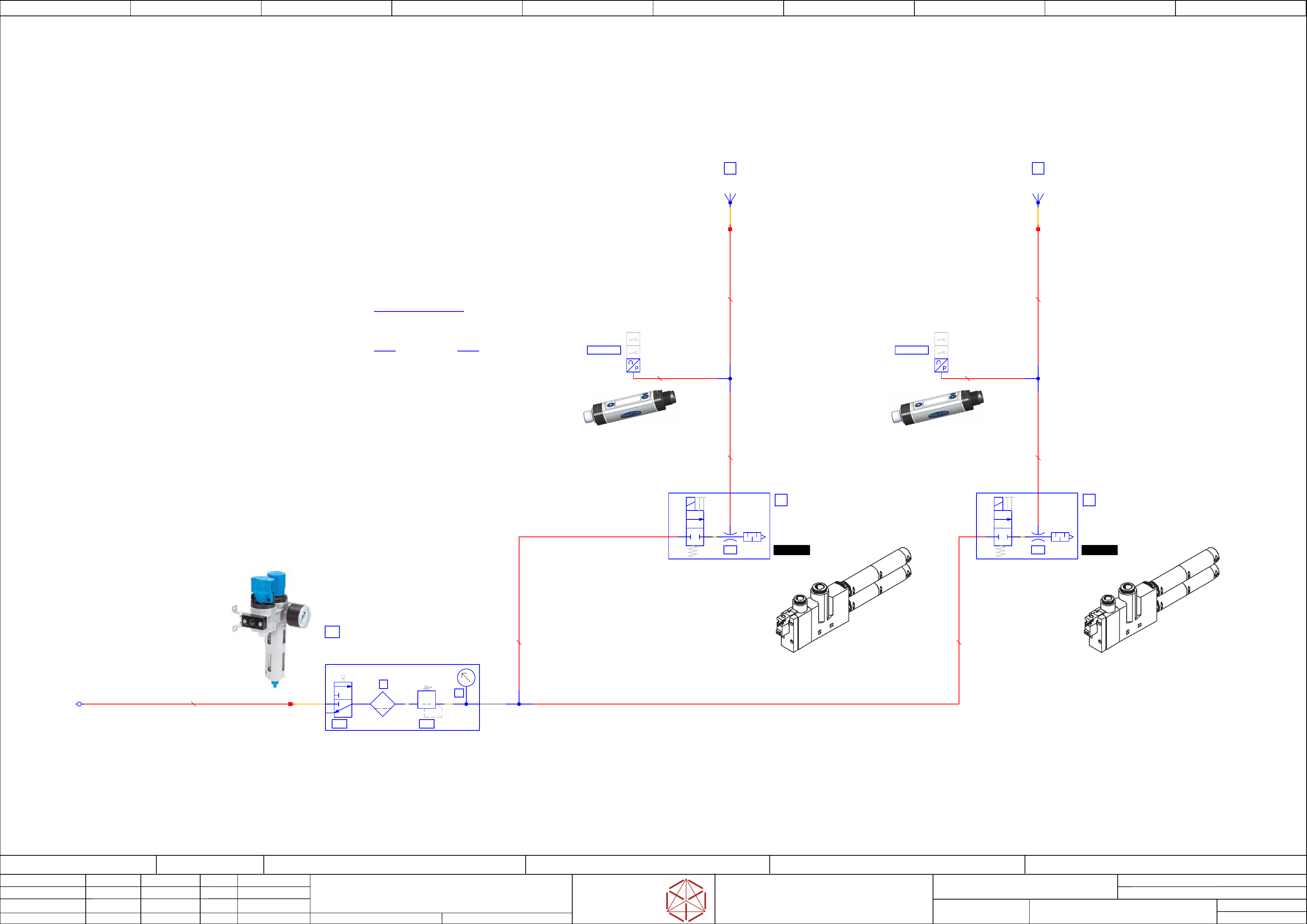
V1.1
1
3
2
manual-actuation
manual-
regulator
V1.2
F1
max 22cm³
U1
U1
U1
U1
Service unit combination
LFR-1/4-D-MINI-KC
03095300
A1
Manometer-pressure
regulated-air 3bar(+-0,1bar)
regulated-
air 3bar(+-0,1bar)
regulated-air 3bar(+-0,1bar)
regulated-air 3bar(+-0,1bar)
-VTL1
main-pressure-distributor
QSL-1/4-10
03082949-
BU10x1,5PVC
00324466-
1
-Y1
/123.5
manual
actuation
3
2
VT1
V1
Vacuum-generator Tooling-L1
Festo: 0010802127
VN-20-H-T6-PQ4-VQ5-RO2-M
03136878
Z1
Vacuum_tooling Lane-1
1
==VT-VS1
Vacuum-sensor Tooling-1
Vacuum-sensor T
ooling-1
Vacuum-sensor Tooling-1
Vacuum-sensor Tooling-1
SCHMALZ: VSi V D M8-4
03118829
/123.3
-VTL11
-VTL11
-
VTL11
-VTL11
1
2
3
QS-12
1
-Y2
/123.6
manual
actuation
3
2
VT2
V2
Vacuum-generator Tooling-L2
Festo: 0010802127
VN-20-H-T6-PQ4-VQ5-RO2-M
03136878
Z2
Vacuum_tooling Lane-2
1
==VT-VS2
Vacuum-sensor Tooling-2
Vacuum-sensor T
ooling-2
Vacuum-sensor Tooling-2
Vacuum-sensor Tooling-2
SCHMALZ: VSi V D M8-4
03118829
/123.4
-VTL12
-VTL12
-
VTL12
-VTL12
1
2
3
-VTL10
1
2
3
00344918
BU12x2PUN
QS-12
00344918
BU12x2PUN
00344918
BU12x2PUN
00344918
BU12x2PUN
00344918
BU12x2PUN
00344918
BU12x2PUN
03121492-
BU4x0,75PVC
03121492-
BU4x0,75PVC
electric_schematic_TX
electric_schematic_TX
electric_schematic_TX
electric_schematic_TX
90012154-010301LE3
Replaced by
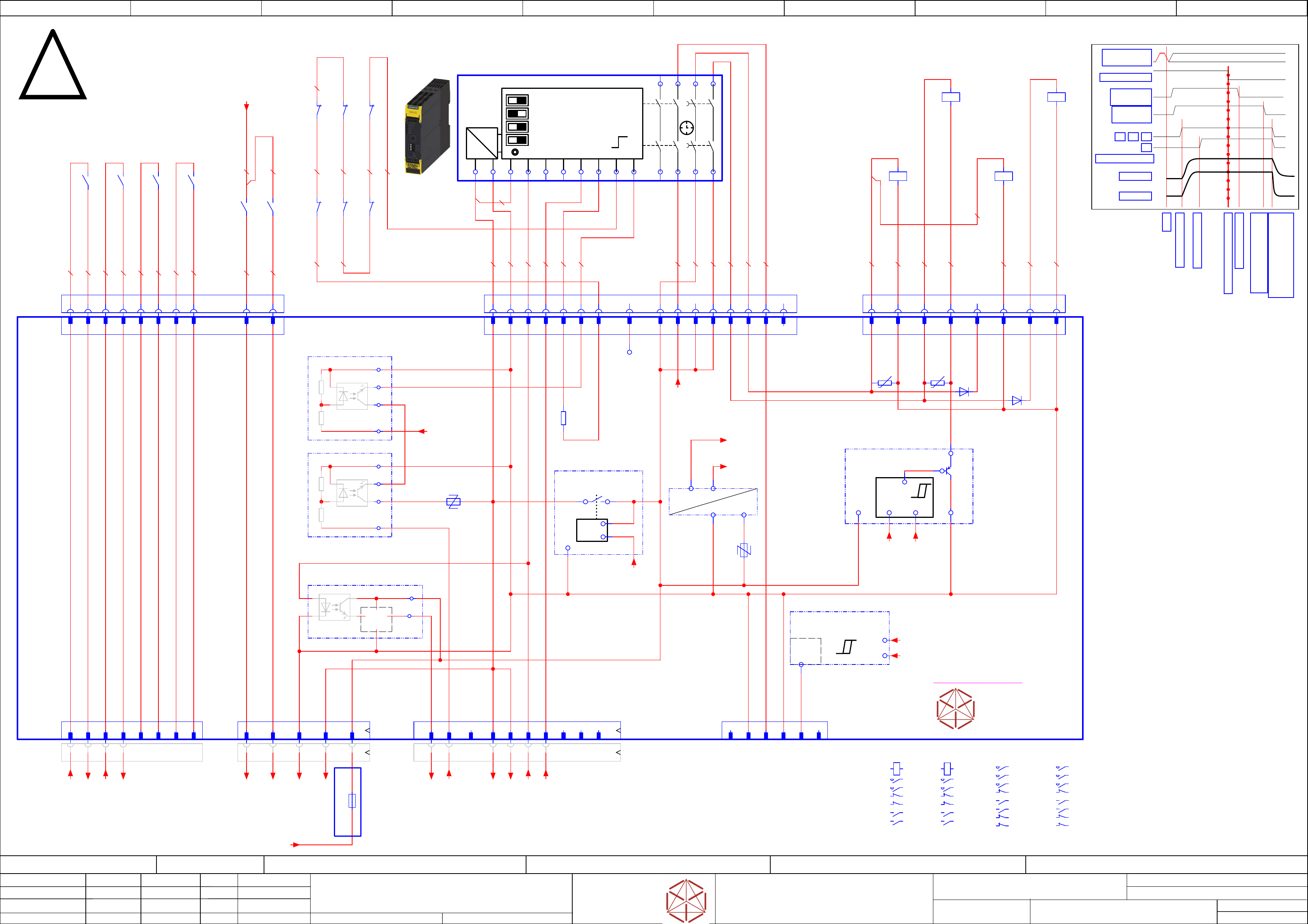
Safety-Loop overview
Safety-Loop overview
Safety-Loop overview
Safety-Loop overview
contactor based safety breaker: logic
contactor based safet
y breaker: logic
contactor based safety breaker: logic
contactor based safety breaker: logic
Replaced by
Weitergabe sowie Vervielfältigung dieser Unterlage, Verwertung und
Mitteilung des Inhalts nicht gestattet, soweit nicht ausdrücklich zugestanden.
Proprietary Data, company confidential.
All rights reserved
Copying of this document, giving it to others and the use or
communication of the contents thereof, are forbidden without express authority.
Doc. No.
0 1 2 3 4 5 6 7 8 9
Privileged business information.
Do not release
Offenders are liable to payment of damages. All rights are reserved in the
event of the grant or the registration of a utility model or design.
Zuwiederhandlungen verpflichten zu Schadenersatz. Alle Rechte vorbehalten,
insbesondere für den Fall der Patenterteilung oder GM-Eintragung vorbehalten.
Page:
Function: Emergency Loop Documentation
==EMG=TX_EMG+CSB/125
drawing number:
03112066-010501LE3
Emergency Loop Documentation
Emer
gency Loop Documentation
Emer
gency Loop Documentation
Emergency Loop Documentation
GmbH & Co KG
ASM
Assembly Systems
Copyright reserved
Ed.
Original
Pingist
Date
Date
Modification
Appr
09.03.2017
Name
Version: Series from
V
ersion: S
eries from
Version: Series from
Version: Series from
2016/Q4 TA500
2016/Q4 TA500
2016/Q4 T
A500
2016/Q4 TA500
starting MC-Nr.: TA500 2016/Q4 G. Pingist
Size DIN A2
Sheet
125
/
1
LOGIC
=~
=
+ -
+ -
+ -
+ -
1 | Autostart/Monitored Start
1 | Autostart/Moni
tored Start
1 | Autostart/Monitored Start
1 | Autostart/Monitored Start
2 | Cross Fault Detection Off/On
2 | Cr
oss F
ault Detection Off/On
2 | Cross Fault Detection Off/On
2 | Cross Fault Detection Off/On
3 | 2 single ch. sensors / 1 double channel Sensor
3 | 2 single ch. sensors / 1 double channel Sensor
3 | 2 single ch. sensors / 1 double channel S
ensor
3 | 2 single ch. sensors / 1 double channel Sensor
4 | Startup Test Yes/No
4 | Startup Test Y
es/No
4 | Startup Test Yes/No
4 | Startup Test Yes/No
SET / RESET
SET / RESET
SET / RESET
SET / RESET
T
T
T
T
- not used -
Parts shown at this page
are for safety related purposes.
To be replaced by
original parts only!
03108631-010301le3
Timing chart
S
S
S
S
Start
Start
Start
Start
Precharge done
Precharge done
Precharge done
Precharge done
Emergency STOP event
Emergency STOP event
Emergency STOP event
Emergency STOP event
K1,K2, K3, K4 off delay;
K1,K2, K3, K4 off delay;
K1,K2, K3, K4 off delay;
K1,K2, K3, K4 off delay;
Discharge external Cap
Discharge external Cap
Dischar
ge external Cap
Discharge external Cap
-->Power off
-->Power off
-->Power off
-->Power off
Safety relais off
Safety relais off
Safety relais off
Safety relais off
Safety relaais off delay
Safety relaais off delay
Safety relaais off delay
Safety relaais off delay
> 100 ms; <180 ms
> 100 ms; <180 ms
> 100 ms; <180 ms
> 100 ms; <180 ms
Precharge start
Precharge start
Precharge start
Precharge start
DC 300 V
DC 300 V
DC 300 V
DC 300 V
DC 160 V
DC 160 V
DC 160 V
DC 160 V
K2
K2
K2
K2
POWER_ENABLE
POWER_ENABLE
POWER_ENABLE
POWER_ENABLE
K1
K1
K1
K1 K4
K4
K4
K4K3
K3
K3
K3
PCC output
PCC output
PCC output
PCC output
delayed
delay
ed
delayed
delayed
PCC output
PCC output
PCC output
PCC output
not delayed
not dela
y
ed
not delayed
not delayed
EMG_Loop_OK
EMG_Loop_OK
EMG_Loop_OK
EMG_Loop_OK
SW_CTRL_ON
SW_CTRL_ON
SW_CTRL_ON
SW_CTRL_ON
Start
Start
Start
Start
Safety_Loop 1&2
Safet
y_Loop 1&2
Safety_Loop 1&2
Safety_Loop 1&2
to Distributor -X22
to Distributor -
X22
to Distributor -
X22
to Distributor -X22
4x Safety Loop Extern
4x Saf
et
y Loop Extern
4x Safety Loop Extern
4x Safety Loop Extern
ITS4141
Load-switch
&
-F1
-F2
24V_PCC
24V_PCC
24V_PCC
24V_PCC
&
GND_Safety
GND_Safet
y
GND_Safety
GND_Safety
ITS4141
Load-switch
&
seperated circuit diagram
A1
INK
IN1
IN2
A2
13
23
37
47
INF
INS
38
48
T2
T1
PAR
-K5
-K5
-K5
-K5
Safety relay 2-chanel
Saf
et
y relay 2-chanel
Safety relay 2-chanel
Safety relay 2-chanel
Safety relay 2NO S=0, 2NO, S=1 (50 ms - 3000ms)
Saf
ety relay 2NO S=0, 2NO, S=1 (50 ms - 3000ms)
Safety relay 2NO S=0, 2NO, S=1 (50 ms - 3000ms)
Safety relay 2NO S=0, 2NO, S=1 (50 ms - 3000ms)
SIE.3SK1121-2CB41
03114826
14
24
Safety Relais connect
-X100.CSB
-X100.CSB
-
X100.CSB
-X100.CSB
-K1
-K1
-K1
-K1
Relay Safety
300V, 160V
A1
A2
A1 A2
1 2
3 4
2221
.2
3132
.2
1413
4443
.1
SIE.3TC4417-0AB4
-K3
-K3
-K3
-K3
Relay Safety
42V, 24V
A1
A2
1 2
3 4
5 6
2221
5453
.0
6463
.0
7271
8281
.2
EAT.DILM17-01(RDC24)
-K4
-K4
-K4
-K4
Relay
Pre-charge
300V, 160V
A1
A2
1 2
3 4
5 6
2122
.2
5453
.1
6463
.1
7271
8281
EAT.DILM17-01(RDC24)
OUT2_ND
DC 24V Safety controlled PL=d
3
GND Safety
8
Loop-CLSD
A5
Loop2-IN
B1
nc
B2
Loop1_IN
A3
Loop ext 1-1
1
Loop ext 1-2
2
Loop ext 2-1
3
Loop ext 2-2
4
Loop ext 3-1
5
Loop ext 3-2
6
Loop ext 4-1
7
Loop ext 4-2
8
A5 B18
GND Safety
2
GND Safety
4
1
1
2
2
3
3
4
4
5
5
6
6
7
7
8
8
9
9
10
10
CH2-OK
16
16
CH1-OK
15
15 5
24V-PCC
B5
24V-PCC
B6
B5
nc
1
PPWR-present
5
nc
6
-A2
-A2
-
A2
-A2
Safety breaker
Safet
y breaker
Safety breaker
Safety breaker
PCB Pre-/discharge assembly
PCB Pr
e-/dischar
ge assembly
PCB Pre-/discharge assembly
PCB Pre-/discharge assembly
-X28.CSB
-X28.CSB
-
X28.CSB
-X28.CSB
AuxContacts
-X28
-X28
-
X28
-X28
AuxContacts in
-X27.CSB
-X27
.CSB
-X27.CSB
-X27.CSB
Safety
contactor
-X30
-X30
-
X30
-X30
Safety
Loop extern
-X24B
-X24B
-X24B
-X24B
Safety
control signals
-X24B.CSB
-X24B.CSB
-X24B.CSB
-X24B.CSB
Safety control
signals to FDB
-W10
-X29.CSB
-X29.CSB
-X29.CSB
-X29.CSB
Safety Loop
& Signals
extern
-W11.1
-X29
-X29
-
X29
-X29
Safety Loop
& Signals
-X31
-X31
-
X31
-X31
Auxiliary
(RFU signals)
-K2
-K2
-K2
-K2
Relay Safety
300V, 160V;
Power enable
A1
A2
A1 A2
1 2
3 4
2221
.2
3231
.2
1413
4344
.2
SIE.3TC4417-0AB4
START_SIG
Safety Start
Signal input
A6
A6
0,75 YE0,75 YE
-K3
-K3
-K3
-K3
81
82
-K4
-K4
-K4
-K4
22
21
-K1
-K1
-K1
-K1
21
22
-K1
-K1
-K1
-K1
32
31
-K2
-K2
-K2
-K2
21
22
-K2
-K2
-K2
-K2
31
32
0,75 YE
0,75 YE 0,75 YE
0,75 YE
0,75 YE
24V0
Safety unit
5
24V_PCC
7
7
nc
A4
nc
B3
nc
B4
B2 B3 B4A4 B6 A3
0,5 PK
0,5 WH
0,5 PK
0,5 PK
0,5 WH
0,5 WH
0,5 PK
0,5 YE
-K3
-K3
-K3
-K3
63
64
-K3
-K3
-K3
-K3
53
54
-K4
-K4
-K4
-K4
53
54
-K1
-K1
-K1
-K1
43
44
0,5 YE
0,5 YE
-K4
-K4
-K4
-K4
63
64
0,5 YE
0,5 YE
0,5 YE
0,5 YE
0,5 BN
0,5 BN
0,5 YE
0,5 YE
0,5 YE
0,5 YE
-K2
-K2
-K2
-K2
44
43
0,5 BN
0,5 WH
0,5 YE
0,5 YE
0,5 YE
0,5 BN
0,5 PK
0,5 PK
0,5 PK
0,5 YE
0,5 BN
0,5 BN
0,5
BN
-X30.CSB
-X30.CSB
-
X30.CSB
-X30.CSB
Safety
Loop Extern
-W11.2
1 2 3 4 5 6 7 8
-F11
-F11
-F11
-F11
Supp1_SSK_RDY
6,3A
6,3A
6,3A
6,3A
A2 Fuse & Distripution
1 2 3 4 5 6 7 8
nc
9 10 11
nc
12 13 14 15 16
nc
15
OUT2_ND
13
OUT2_D
16
nc
1
K1-A1
1 2
2
GND
8
8
GND
14
OUT1_D
6
6
GND
5
5
A3-K1
7
7
K4-A1
-X100
-X100
-
X100
-X100
Safety relais connect
-X27
-X27
-
X27
-X27
Safety
contactor
3 4
3
K2-A1
4
GND/K5
-R42
60VAC(100mW)
-R43
60VAC(100mW)
-D18
1
24V_PCC
2
GND
3
Loop1_IN
4
Loop2_IN
5
T2
6
START
7
TestLoopIn
8
nc
-R128
0R
Test_loop_IN
+
+
-
-K1
-K1
-K1
-K1
Safety loop
closed signal
24V0
L_CLSD
9
24V0
10
24Vext
11
24V0
12
24V0
-D50
-P300.pbc
-P300.pbc
-P300.pbc
-P300.pbc
Voltage-Trigger
300V precharge bypass control
Out
GND
24V0
24V.Safe
24V.Saf
e
24V.Safe
24V.Safe
Safe DC
internal supply
24VSafe
24V0
-K2
-K2
-K2
-K2 Start_loop
-
+
+
in
out
GND
DIAGN_K_N
-K3
-K3
-K3
-K3 Start_loop
-
+
+
in
out
GND
START_SIG
24V_PCC
24V_PCC
24V_PCC
24V_PCC
PCC supply
undervoltage lockout
OUT
24V_PCC
IN
24V0
DIAG
U_Mon
-Out
-PPWR.PRESENT
-PPWR.PRESENT
-PPWR.PRESENT
-PPWR.PRESENT
Voltage-Trigger
300V/160V PPWR-present
(300V > 60V & 160V > 60V)
P300V
P160V
-DI0_Safety_Loop_OK
+DI/126.1
-Loop2-End
-Loop2-End
-Loop2-End
-Loop2-End
+DI/126.1
-Loop1_Begin
-Loop1_Begin
-Loop1_Begin
-Loop1_Begin
+DI/126.1
-Safety_Start_SSK
+DI/126.1
-Loop2_Begin
-Loop2_Begin
-Loop2_Begin
-Loop2_Begin
+DI/126.1
-Loop1-End
-Loop1-End
-Loop1-End
-Loop1-End
+DI/126.1
==+-24V_F12_Aux
-Safety_Loop1_ext.in
+DI/126.2
-Safety_Loop1_ext.out
+DI/126.2
-Safety_Loop2_ext.in
+DI/126.2
-Safety_Loop2_ext.out
+DI/126.2
-GND_1
-CH1-OK
-CH2-OK
-PCC-POWER-OK
DC 24 V
from Power Supply PS4
24V-Supply
-P300V
-P160V
VDIFFMON1
300V
VDIFFMON2
160V
24VSafe
Safe supply
P_GND
Power Ground
DIAGN_K_N
==CSB=TX+/42.5
DIAGN_RD_N