00198274-02_DC_SIPLACE_TX-Series_DE+EN.pdf - 第7页
Sheet Size DIN A3 electric_schematic_TX Ed. Original Pingist Function Date Date Replaced by <Empty identifier> T able of contents : ==GAm=TXm+GA1/111 - ==EMG=TX_EMG+DI/128 Modification Appr Replaced by 07 .11.2017 …
Sheet
Size DIN A3
electric_schematic_TX
Ed.
Original
Pingist
Function
Date
Date
Replaced by
<Empty identifier>
Table of contents : ==HD=TX+TWIN_1/83 -
==CHm=TXm+GA/110
Modification
Appr
Replaced by
07.11.2017
2.3
Page
Name
Weitergabe sowie Vervielfältigung dieser Unterlage, Verwertung und Mitteilung des Inhalts nicht gestattet, soweit nicht ausdrücklich zugestanden.
Proprietary Data, company confidential. All rights reserved
Copying of this document, giving it to others and the use or communication of the contents thereof, are forbidden without express authority.
GmbH & Co KG
ASM
Assembly Systems
Copyright reserved
Privileged business information. Do not release
Offenders are liable to payment of damages. All rights are reserved in the event of the grant or the registration of a utility model or design.
Zuwiederhandlungen verpflichten zu Schadenersatz. Alle Rechte vorbehalten, insbesondere für den Fall der Patenterteilung oder GM-Eintragung vorbehalten.
==INTRO/2.3
/
6
drawing number:
Doc. No.
Page description supplementary page fieldPage Edited by
Table of contents
Mounting
location
AS-F06_002
DateFunction
90012154-010301LE3
Pingist09.03.2017TWIN1-Head main_board_1TWIN_1HD TWIN_Head 83
Pingist09.03.2017TWIN1-Head force_measurement_board_1TWIN_1HD TWIN_Head 84
Pingist09.03.2017TWIN2-Head main_board_2TWIN_1HD TWIN_Head 85
Pingist09.03.2017TWIN2-Head force_measurement_board_2HD TWIN_Head TWIN_1 86
Pingist09.03.2017Control-wiring-board-ao "Lane-1"L1CO008 Dual_Conveyor_TX 87
Pingist09.03.2017Control-wiring "Lane-1" sensoric for side-panel-A/BL1CO008 Dual_Conveyor_TX 88
Pingist09.03.2017Motor-wiring-M1/M2 "Lane-1"CO008 Dual_Conveyor_TX L1 89
Pingist09.03.2017Motor-wiring-M3/M4 "Lane-1"L1CO008 Dual_Conveyor_TX 90
Pingist09.03.2017Motor-wiring-M5 breadth-adjusting "Lane-1"L1CO008 Dual_Conveyor_TX 91
Pingist09.03.2017Control-wiring-board-ap "Lane-2"L2CO008 Dual_Conveyor_TX 92
Pingist09.03.2017Control-wiring "Lane-2" sensoric for side-panel-C/DCO008 Dual_Conveyor_TX L2 93
Pingist09.03.2017Motor-wiring-M6/M7 board-A2 "Lane-2"CO008 Dual_Conveyor_TX L2 94
Pingist09.03.2017Motor-wiring-M8/M9 board-A2 "Lane-2"CO008 Dual_Conveyor_TX L2 95
Pingist09.03.2017Motor-wiring-M10 breadth-adjusting "Lane-2"CO008 Dual_Conveyor_TX L2 96
Pingist09.03.2017Code_Reader_Lector620 PCB_Transfer Lane_1CR Code_Reader Lector_620 Lector620 97 ***Optional***
Pingist09.03.2017Gantry 1 Trailing interface, VBIGA TXmicron > Modification Scanning-headCHm Cable_Harness TX_micron 108
Pingist09.03.2017Gantry 2 MGCU, Trailing interfaceGA TXmicron > Modification Scanning-headCHm Cable_Harness TX_micron 109
Pingist09.03.2017Code_Reader_Lector620 PCB_Transfer Lane_2 ** Optional Dual-Conveyor only **Lector620CR Code_Reader Lector_620 98 ***Optional***
Pingist09.03.2017JTF_Connection TXJTF JEDEC Table Feeder Connection 99 ***Optional***
Pingist07.11.2017Main_Pneumatics_UnitFLUID FLUID 100
Pingist16.08.2017Pneumatics-tubing Gantry 1-2 with CP20P-Head & Vacuum_pumpFLUID FLUID 101
Pingist16.08.2017Pneumatics-tubing Gantry 1-2 with Option CPP-Head & TWIN-Head / without Vacuum_pumpFLUID FLUID 102
Pingist07.11.2017Pneumatics-tubing COT-insert & Tape-CutterFLUID FLUID 103
107 Pingist09.03.2017Gantry 1 MGCU, Trailing interfaceGA TXmicron > Modification Scanning-headCHm Cable_Harness TX_micron
104 Pingist09.03.2017Gantry 1 _ CP20-Head / TWIN-HeadGAm TXmicron > Modification Scanning-headOVm Gantry TX_micron
105 Pingist09.03.2017Gantry 2 _ CPP-HeadGAm TXmicron > Modification Scanning-headOVm Gantry TX_micron
106 Pingist09.03.2017Block_diagram CP20p_M2 HeadHD TXmicron > OptionalOVm CP20p_M2 Head
110 Pingist09.03.2017Gantry 2 Trailing interface, VBIGA TXmicron > Modification Scanning-headCHm Cable_Harness TX_micron
Sheet
Size DIN A3
electric_schematic_TX
Ed.
Original
Pingist
Function
Date
Date
Replaced by
<Empty identifier>
Table of contents : ==GAm=TXm+GA1/111 -
==EMG=TX_EMG+DI/128
Modification
Appr
Replaced by
07.11.2017
2.4
Page
Name
Weitergabe sowie Vervielfältigung dieser Unterlage, Verwertung und Mitteilung des Inhalts nicht gestattet, soweit nicht ausdrücklich zugestanden.
Proprietary Data, company confidential. All rights reserved
Copying of this document, giving it to others and the use or communication of the contents thereof, are forbidden without express authority.
GmbH & Co KG
ASM
Assembly Systems
Copyright reserved
Privileged business information. Do not release
Offenders are liable to payment of damages. All rights are reserved in the event of the grant or the registration of a utility model or design.
Zuwiederhandlungen verpflichten zu Schadenersatz. Alle Rechte vorbehalten, insbesondere für den Fall der Patenterteilung oder GM-Eintragung vorbehalten.
==INTRO/2.4
/
6
drawing number:
Doc. No.
Page description supplementary page fieldPage Edited by
Table of contents
Mounting
location
AS-F06_002
DateFunction
90012154-010301LE3
Pingist09.03.2017Motor-YGAm Gantry_1 TX_micron GA1 TXmicron > Modification Scanning-head111
Pingist09.03.2017Head-Interface-1GAm Gantry_1 TX_micron GA1 TXmicron > Modification Scanning-head112
Pingist09.03.2017Motor-XGAm Gantry_1 TX_micron GA1 TXmicron > Modification Scanning-head113
Pingist09.03.2017Vision and GigEGAm Gantry_1 TX_micron TXmicron > Modification Scanning-headGA1 114
Pingist09.03.2017Placement-Head CP20 and Component-Camera & PCB-CameraGAm Gantry_1 TX_micron GA1 TXmicron > Modification Scanning-head115
Pingist09.03.2017Motor-YGA2 TXmicron > Modification Scanning-headGAm Gantry_2 TX_micron 116
Pingist09.03.2017Head-Interface-2GA2 TXmicron > Modification Scanning-headGAm Gantry_2 TX_micron 117
Pingist09.03.2017Motor-XGA2 TXmicron > Modification Scanning-headGAm Gantry_2 TX_micron 118
Pingist09.03.2017Vision and GigEGA2 TXmicron > Modification Scanning-headGAm Gantry_2 TX_micron 119
Pingist09.03.2017Placement-Head CPP and Component-Camera & PCB-CameraGA2 TXmicron > Modification Scanning-headGAm Gantry_2 TX_micron 120
Pingist09.03.2017CP20p-M2 Head Intermediate Distributor CP20pCP20p_M2 TXmicron > OptionalHDm CP20p-M2 Head 121
Pingist09.03.2017CP20p-M2 Head Intermediate Distributor CP20p StarCP20p_M2 TXmicron > OptionalHDm CP20p-M2 Head 122
Pingist09.03.2017Vacuum_tooling03149194_0301 TXmicron > OptionalVT Vacuum tooling TX_micron 123
Pingist09.03.2017Fluid Vacuum_tooling03149194_0301 TXmicron > OptionalVT Vacuum tooling TX_micron 124
125 Pingist09.03.2017Safety-Loop overview contactor based safety breaker: logicCSB single circuit diagramEMG Emergency Loop Documentation
126 Pingist09.03.2017Safety-Loop overview Emergency-Stop Start/Stop-ButonDI single circuit diagramEMG Emergency Loop Documentation
127 Pingist09.03.2017Safety-Loop overview Hood-switchDI single circuit diagramEMG Emergency Loop Documentation
128 Pingist09.03.2017Safety-Loop overview COTi Safety & SignalingDI single circuit diagramEMG Emergency Loop Documentation
electric_schematic_TX
electric_schematic_TX
electric_schematic_TX
electric_schematic_TX
90012154-010301LE3
Replaced by
Graphics top-view
Graphics top-view
Graphics top-view
Graphics top-view
inside-modules
inside-modules
inside-modules
inside-modules
Replaced by
Weitergabe sowie Vervielfältigung dieser Unterlage, Verwertung und
Mitteilung des Inhalts nicht gestattet, soweit nicht ausdrücklich zugestanden.
Proprietary Data, company confidential.
All rights reserved
Copying of this document, giving it to others and the use or
communication of the contents thereof, are forbidden without express authority.
Doc. No.
Privileged business information.
Do not release
Offenders are liable to payment of damages. All rights are reserved in the
event of the grant or the registration of a utility model or design.
Zuwiederhandlungen verpflichten zu Schadenersatz. Alle Rechte vorbehalten,
insbesondere für den Fall der Patenterteilung oder GM-Eintragung vorbehalten.
Page:
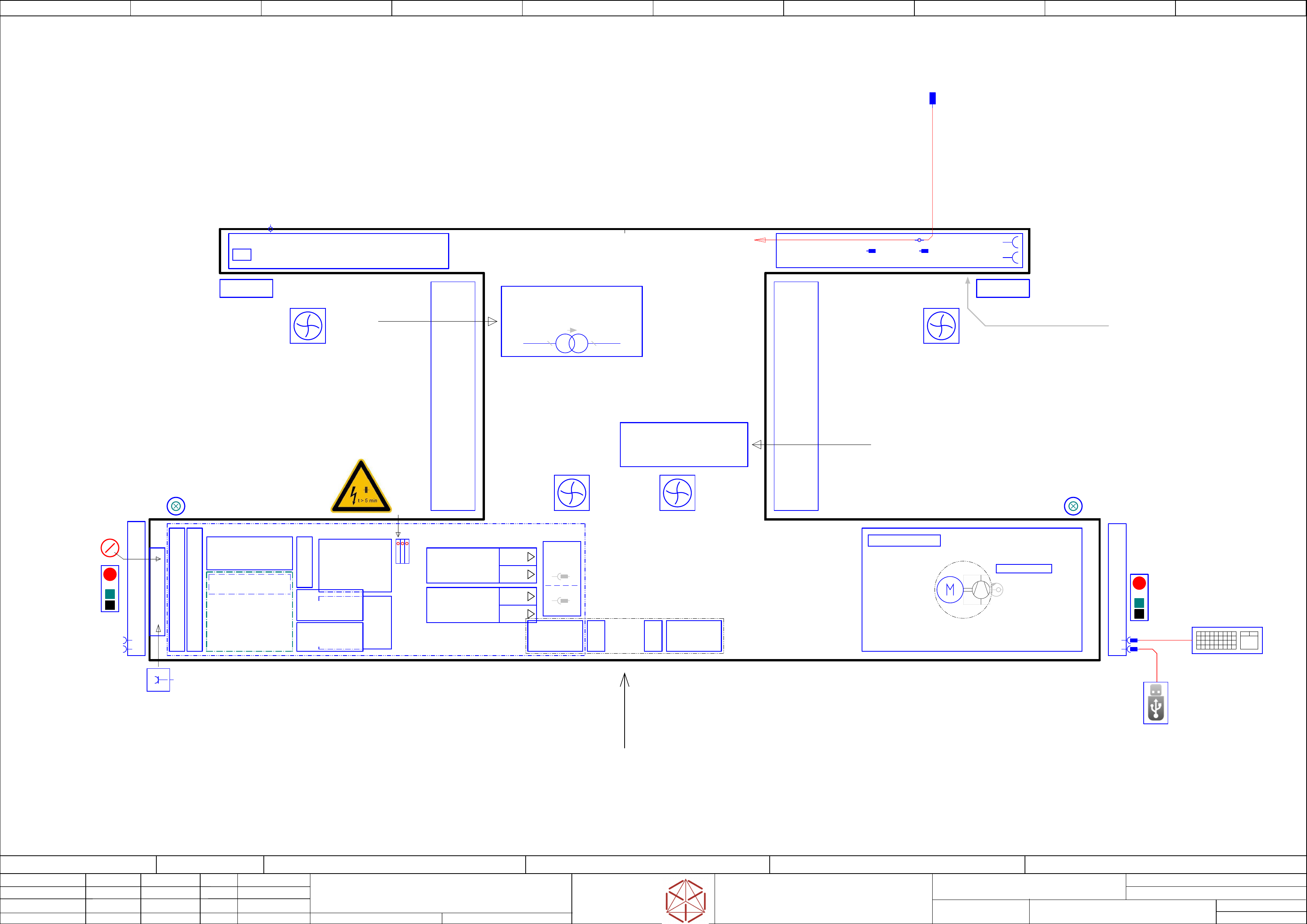
Function: Overview Graphics
==OVGR=TX/3
drawing number:
03110650-010201LE3
overview_graphics
o
v
erview_graphics
overview_graphics
overview_graphics
GmbH & Co KG
ASM
Assembly Systems
Copyright reserved
Ed.
Original
Pingist
Date
Date
Modification
Appr
09.03.2017
Name
Version: Series from
V
ersion: S
eries from
Version: Series from
Version: Series from
2016/Q4 TA500
2016/Q4 TA500
2016/Q4 T
A500
2016/Q4 TA500
starting MC-Nr.: TA500 2016/Q4 G. Pingist
Size DIN A2
Sheet
3
/
1
Location 1
Location 1
Location 1
Location 1Location 2
Location 2
Location 2
Location 2
Main switch
Start
Emergency Stop
Stop
Start
Stop
Emergency Stop
Fan Flap 2
Fans
- Basic protection -
Fan Flap 1
PCB Transfer
Sercice_access
Sercice_access
Interface Extern Connections
Interface Extern Connections
Interface Extern Connections
Interface Extern Connections
-DIC
-FDC
Connector-
Field
3Ph/Mot4
3Ph/Mot3
3Ph/Mot2
3Ph/Mot1
USB keyboard with touch pad
(only for service)
==CH+CTRL/54.03
Service Testing-Point
DC 300 V IN/OUT
==PS005+ELS/38.03
ELS(electric_slide_in) SMPS & MGCU unit
ELS(electric_slide_in) SMPS & MGCU unit
ELS(electric_slide_in) SMPS & MGCU unit
ELS(electric_slide_in) SMPS & MGCU unit
- above -
==FLUID-M1.VAC
==FLUID-VAC_P
Vacuum_Pump
- Optional -
==FLUID/101.01
-U1
-U1
-U1
-U1
Pneumatic-group P001
Main_Pneumatics_connection
Main_valves
3Ph 400V
Transformer
Tr
ansformer
Transformer
Transformer
US voltage adaption kit (Option)
US voltage adaption kit (Option)
US voltage adaption kit (Option)
US voltage adaption kit (Option)
3P208V/400V/5,05A
==MPI/37.00
3Ph 200V
-PC
-PC
-PC
-PC
Control computer BoxPC-427D i3 2xPCIe
03114177
==CH+CTRL/54.02
4x SMEMA-Interface
==CO008+L1/87.07
LAN2 extern_Connection
RJ45
==CH+CTRL/54.05
-X1
-X1
-
X1
-X1
Mains Connection
Mains Connection
Mains Connection
Mains Connection
CEE-connector
5-pole 6h 16A/400V
==MPI/37.03
Main-connection
Main-connection
Main-connection
Main-connection
air-pressure
air-pressure
air-pressure
air-pressure
p= 5 to 10bar
by 500NL/min
Service Socket
230VAC(110VAC)
10A
==MPI/37.04
1/N/PE
CAN Interface CIN
==CH+CTRL/54.00
-MGCU2
-MGCU2
-MGCU2
-MGCU2
Position controller MGCU
Gantry 2 axis X/Y
==CH+GA/57.00
-MGCU1
-MGCU1
-MGCU1
-MGCU1
Position controller MGCU
Gantry 1 axis X/Y
==CH+GA/55.00
Fuse- and Distribution PCB
==PS005+ELS/39.00
CAN- I/O control unit III
==DI/43.00
Main Power Input
==MPI/37.02
Monitor-2
Monitor-2
Monitor-2
Monitor-2
==CH+CTRL/54.05
USB A plug
USB-STICK 3.0(2.0)
Service (Data-handling)
==CH+CTRL/54.05
Control-elements-1
==CH+DI/49.00
Control-elements-2
==CH+DI/49.03
USB
Monitor-1
Monitor-1
Monitor-1
Monitor-1
==CH+CTRL/54.01
USB
Service
Fault indicator lamp 2
==CH+DI/52.05
Fault indicator lamp 1
==CH+DI/52.03
Hood switch S2
==CH+DI/50.04
Hood switch S1
==CH+DI/50.01
-CAP1
-CAP1
-CAP1
-CAP1
DC 300/150
Capacitor Bank
==PS005+ELS/38.00
==CSB+#
==CSB+#
==CSB+#
==CSB+#
Contactor Safety Bracker
+ELS/4 ==OV+PE/11.01 ==OV+PS005/13.04
-A2
Safety breaker
PCB Pre-/discharge assembly
==CSB/41.00
-PS3
-PS3
-PS3
-PS3
DC Out 27V/20A (COTi)
==PS005+ELS/39.02
-PS4
-PS4
-PS4
-PS4
DC Out 24V/20A (Control)
==PS005+ELS/39.03
-PS1
-PS1
-PS1
-PS1
Motion DC-Out1 300V
DC-Out2 160V
==PS005+ELS/38.00
-PS2
-PS2
-PS2
-PS2
DC-out 42V / 960W
==PS005+ELS/39.01
-TI1
-TI1
-TI1
-TI1
Trailing interface 1
==CH+GA/55.00
-TI2
-TI2
-
TI2
-TI2
Trailing interface 2
==CH+GA/57.00
-VBI1
-VBI1
-VBI1
-VBI1
Vision
Base-Interface 1
==CH+GA/56.05
-VBI2
-VBI2
-VBI2
-VBI2
Vision
Base-Interface 2
==CH+GA/58.05
-X2
-FCU
-FCU
-FCU
-FCU
X-FCU V2
X
-FCU V2
X
-FCU V2
X-FCU V2
Location-1
Location-1
Location-1
Location-1
==COTi+Loc1/60.00
-FCU
-FCU
-FCU
-FCU
X-FCU V2
X
-FCU V2
X
-FCU V2
X-FCU V2
Location-2
Location-2
Location-2
Location-2
==COTi+Loc2/63.00
2x Shuttle-Interface
==CH+PS/48.01
CAN3.EXT
access to Shuttle connection