manual-jtse-control-unit-hot-air--0027698_ID-218375_EN.pdf - 第11页
TC Suc tion O K 17:14 20 ºC Power 45% 120ºC Selected T C T emp. 4m 38s 400 ºC 80 % 400ºC Selected Protection Hot Air T emp. Air Flow Selec. TC Suc tion O K JT T TE T JT TE Use on ly with a 250V fu se Emp lo y er u n iq u…
TC
Suction
OK
17:14
20
ºC
Power
45%
120ºC Selected
TC
Temp.
4m 38s
400
ºC
80
%
400ºC Selected
Protection
Hot Air Temp. Air Flow Selec.
TC
Suction
OK
JTT
TET
JT
TE
Use only with a 250V fuse
Employer uniquement avec
un fusible de 250V
TC
Suction
OK
TC
Suction
OK
17:14
20
ºC
Power
45%
120ºC Selected
TC
Temp.
4m 38s
400
ºC
80
%
400ºC Selected
Protection
Hot Air Temp. Air Flow Selec.
TC
Suction
OK
JTT
TET
JT
TE
Use only with a 250V fuse
Employer uniquement avec
un fusible de 250V
TC
Suction
OK
1010
Using the Thermocouple Type K
You can choose from two work modes:
Regulation: the station regulates the air
the temperature automatically to maintain the
External Thermocouple (TC) temperature.
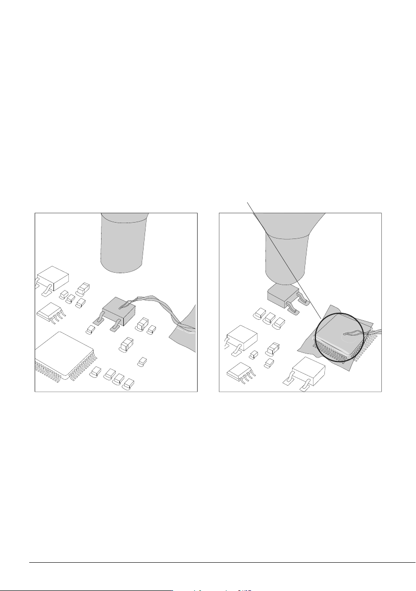
It is not recommended to exceed ramp-up rates over 3-4ºC / sec. (5-7ºF / sec) so as to reduce the
risk of thermal stress on the PCB.
Fix the TC with Kapton Tape (Ref. PH217) as near as possible to the component being worked on.
If Kapton tape is not ESD you must use an ionizer.
Protection: the station cuts the air supply off
when the External Thermocouple (TC)
temperature is reached.
Connect a TC type K (PH218) to the station and use it as a protection or regulation sensor.
You can define its use mode by means of the “Ext TC mode” option in the “Tool” menu.
TC
Suction
OK
17:14
20
ºC
Power
45%
120ºC Selected
TC
Temp.
4m 38s
400
ºC
80
%
400ºC Selected
Protection
Hot Air Temp. Air Flow Selec.
TC
Suction
OK
JTT
TET
JT
TE
Use only with a 250V fuse
Employer uniquement avec
un fusible de 250V
TC
Suction
OK
TC
Suction
OK
17:14
20
ºC
Power
45%
120ºC Selected
TC
Temp.
4m 38s
400
ºC
80
%
400ºC Selected
Protection
Hot Air Temp. Air Flow Selec.
TC
Suction
OK
JTT
TET
JT
TE
Use only with a 250V fuse
Employer uniquement avec
un fusible de 250V
TC
Suction
OK
NH
NH
NH
NHS (NH)
JTS
TES
JTT
JTT
JTT
NH
NH
NH
NHS (NH)
JTS
TES
JTT
JTT
JTT
1111
40 mm
50 mm
60 mm
80 mm
100 mm
130 mm
130 mm
para manuales - color gris
200 mm
300 mm
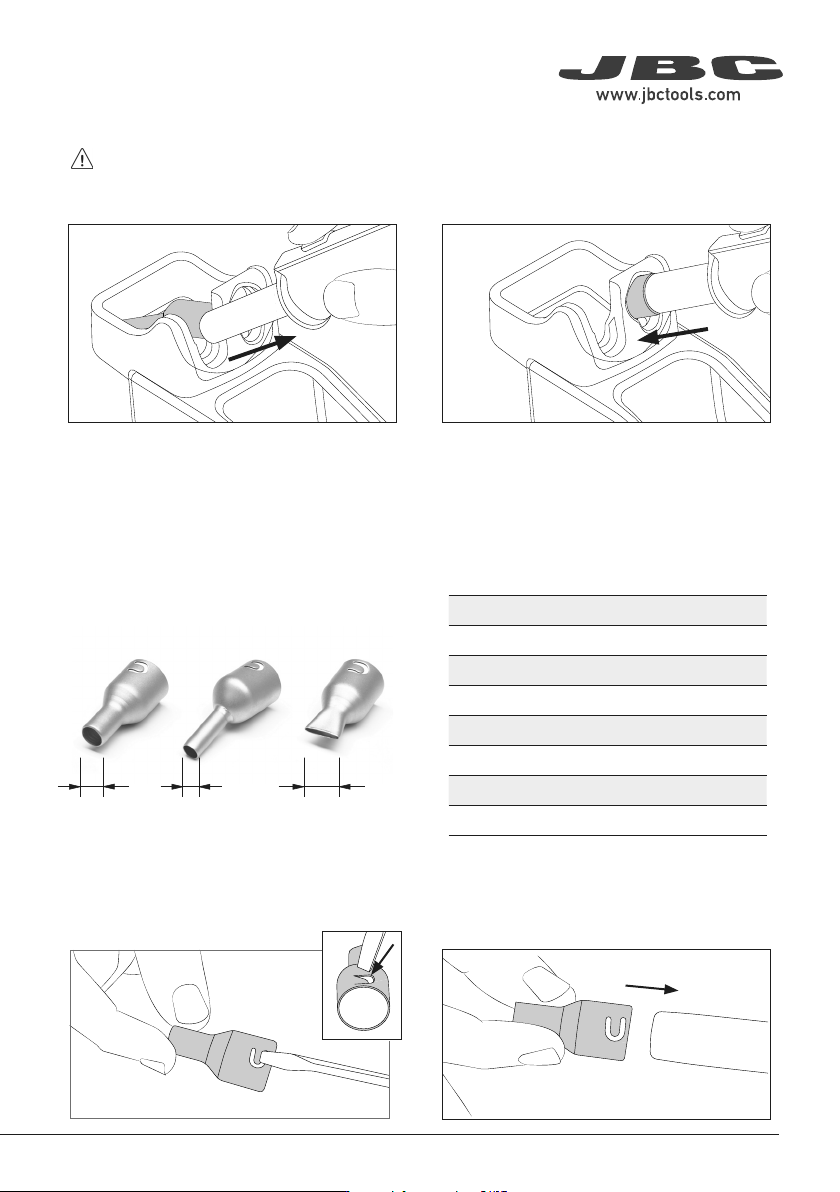
In case of a loosely fitting nozzle:
* Ref. Shape Size
(mm)
Size
(in)
* JN2020 Straight Ø 8 Ø 0.31
JN8417 Straight Ø 10 Ø 0.4
* JN2015 Bent Ø 4 Ø 0.16
* JN2012 Bent Ø 6 Ø 0.24
JN6633 Bent Ø 8 Ø 0.31
JN7637 Flat 10 x 2 0.39 x 0.08
JN7638 Flat 20 x 2 0.79 x 0.08
JN7639 Flat 30 x 2 1.18 x 0.08
Straight Bent Flat
Ø Ø A x B
1. Push the nozzle tab inwards with a screw-
driver or flat-nosed pliers.
2. Assemble the nozzle onto JTT again.
Nozzle Exchanger
Turn the tool off and handle with care. The heating element and the nozzle are still hot.
Compatible Nozzles
JTT works with JN nozzles. Find the model that
best suits your soldering needs at www.jbctools.
com
* Supplied with JTSE Station
Place the heating element with its nozzle in the
nozzle changer and pull the tool to remove it.
The nozzle comes to rest in the nozzle holder.
Attach the nozzle and press the nozzle onto the
heating element with the help of the opening
in the nozzle exchanger.
1. Removing Nozzle 2. Attaching Nozzle
TC
Suction
OK
17:14
20
ºC
Power
45%
120ºC Selected
TC
Temp.
4m 38s
400
ºC
80
%
400ºC Selected
Protection
Hot Air Temp. Air Flow Selec.
TC
Suction
OK
JTT
TET
JT
TE
Use only with a 250V fuse
Employer uniquement avec
un fusible de 250V
TC
Suction
OK
12
1
2
1
2
12
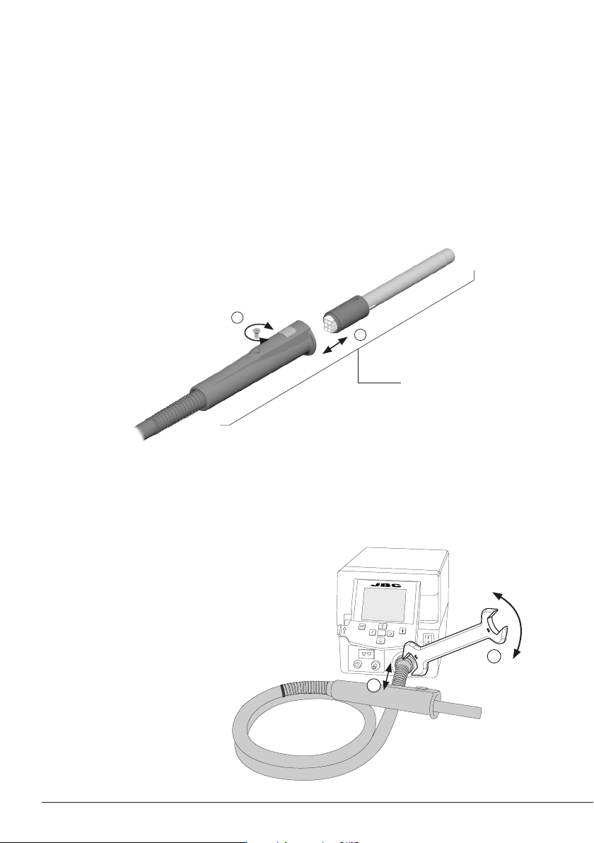
Note: Only perform this operation when the element is cold and the unit is disconnected from the
mains.
Loosen the screw (1) and pull the worn heating element out of the handle (2).
Insert the new heating element, make sure its pushed all the way in (2) and tighten the screw (1).
Replacing the Heating Element
JTT
Heater Hose Set
Ref. JT-T1A (100V / 120V)
JT-T2A (230V)
JTH
Heating Element for JTT
JTH1: Ref. 0014105 (100V and 120V)
JTH2: Ref. 0014107 (230V)
Handle for JTT
Ref. JT-A (100V / 120V / 230V)
Changing the JTT Heater Hose Set
Note: Only perform this operation when the
station is turned off.
Use a spanner to unscrew the nut (1) and
remove the tool hose from the control unit (2).
Insert the new hose, make
sure it is pushed all the way
into the connector (2), and
tighten the nut (1).