09_SM481_Service_Manual Feeder_Base.pdf - 第9页
F eeder Base 9-5 9.2. Feeder Base Mod ule 9.2.1. Require d T ool s W rench T wre nch (other tool s supplied) o r he x w r ench Screw d r iver with “ + ” shaped tip 9.2.2. Feed er base m o dul e Replacem ent Proced …
Advanced High Speed Flexible Mounter
9-4
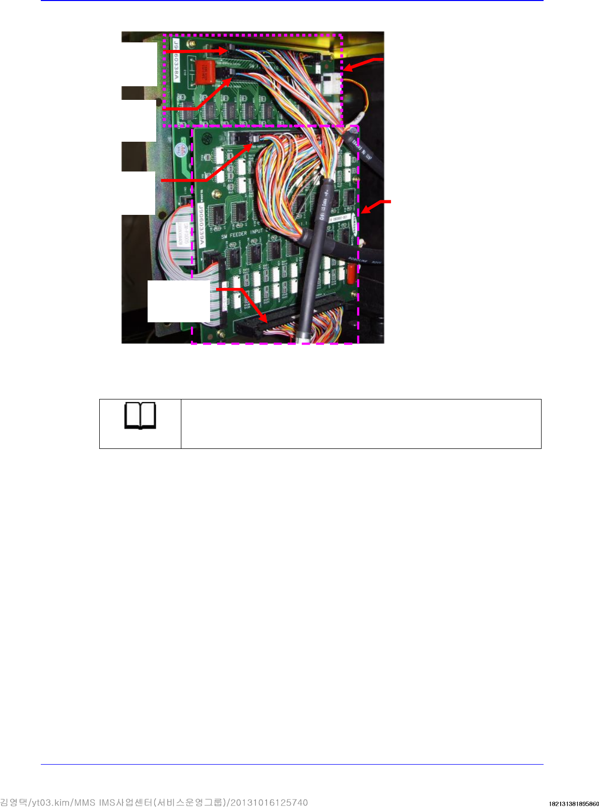
3. Disconnect the connectors connected to the Feeder Control Board and Feeder Input EXT Board.
4. Unscrew the fixing bolts securing the board using a hex wrench and remove it.
5. Replace the board with a new one.
Reference
The part number of the board is AM03-000819A, J91741071A
6. The assembling is performed in the reverse order of disassembling.
Left Feeder
Base Board
Output
Right Feeder
Base Board
Output
Left Feeder
Base Board
Input
Right Feeder
Base Board
Input
Rear Feeder
IO Board
Feeder Extension
Board
Feeder Base
9-5
9.2. Feeder Base Module
9.2.1. Required Tools
Wrench
T wrench (other tools supplied) or hex wrench
Screw driver with “+” shaped tip
9.2.2. Feeder base module Replacement Procedure
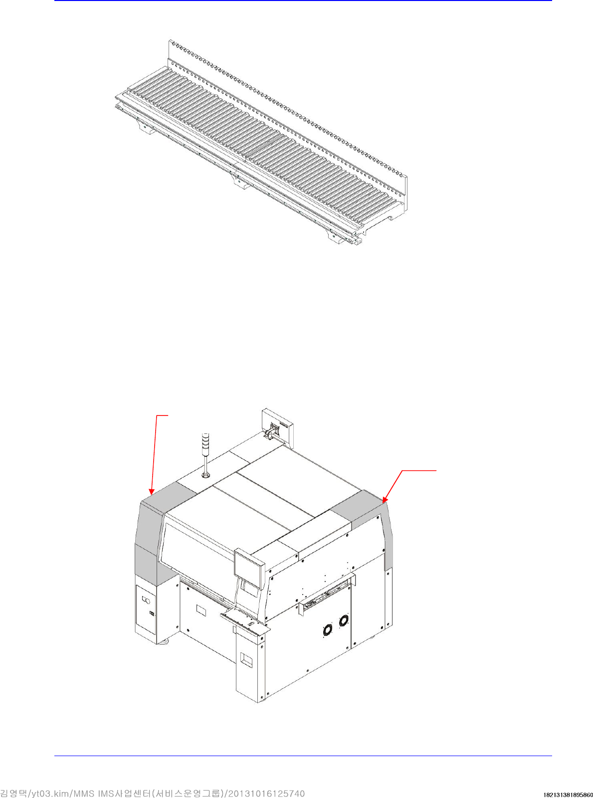
1. Turn Off the PC in normal way. Then turn off the main switch on the front side of the machine.
2. Unscrew the fixing screws securing the cover and remove it using a crosshead (Phillips)
screwdriver.
Upper RL Cover
Upper FL Cover
Advanced High Speed Flexible Mounter
9-6
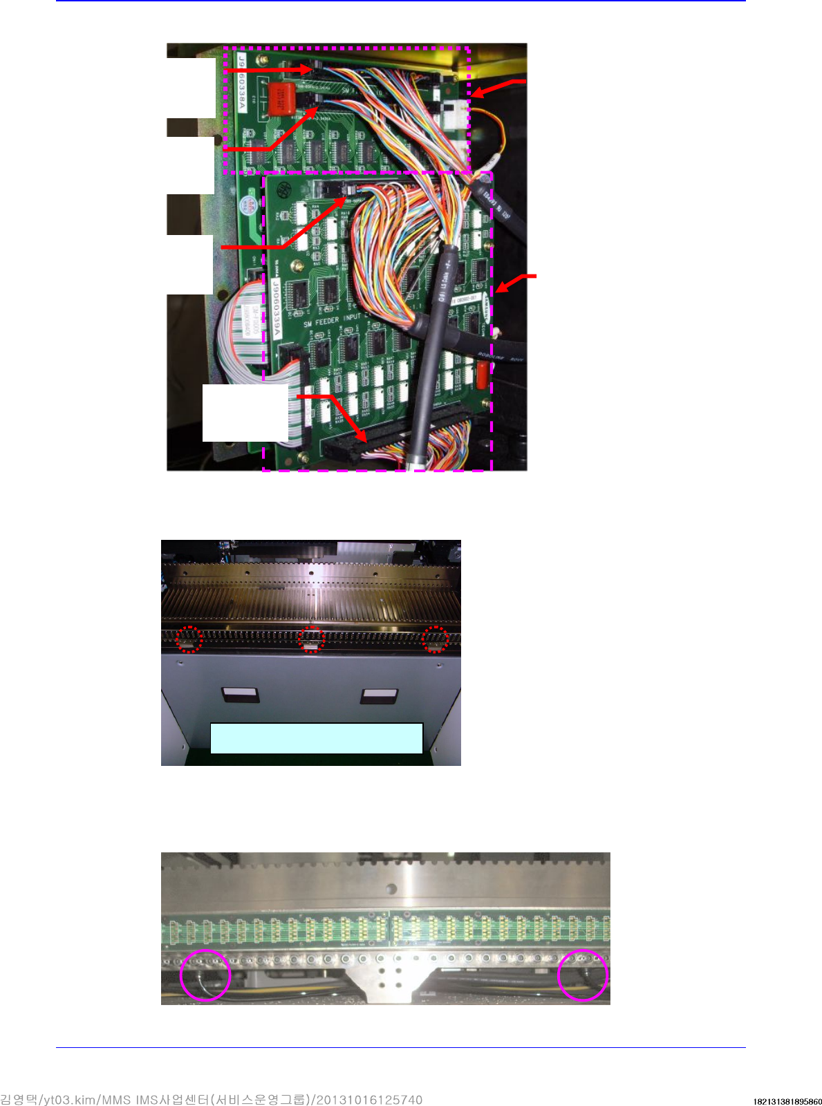
3. Disconnect the connectors connected to the Feeder Control Board and Feeder Input EXT Board.
4. Unscrew the fixing screws (M8- 3 sets) to remove the Front Cover-Feeder Station Con-Panel
Front.
5. In order to facilitate the removal of the air tube connected to the feeder base module, turn the
fitting to which the air tube is connected downward manually as shown in the following figure
to remove the air tube.
Left Feeder
Base Board
Output
Right Fee
der
Base Board
Output
Left Feeder
Base Board
Input
Right Feeder
Base Board
Input
Rear Feeder
IO Board
Feeder Extension
Board
Remove fixing screws (3 sets)