20200227103734031.pdf - 第19页
硬质合金机夹刀片 Cemented Carbide Indexable Inserts B 研磨铣刀片的表示 Code key for ground milling inserts 研磨铣刀片型号由型式代号,铣刀片代号(包括切削刃后角代号)和内切圆直径 数字代号组成必要时再缀以左切刀(z)或右切刀(Y) The code for ground milling inserts consists of the code for the ty…
硬质合金机夹刀片
Cemented Carbide Indexable Inserts
B
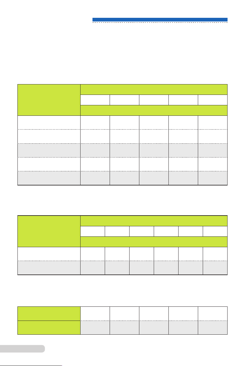
(3) 机夹刀片毛坯厚度的尺寸系列
(3)
The thickness of indexable inserts blanks
带孔机夹刀片毛坯厚度尺寸系列按表1规定
The thickness of inserts blanks with holes as per Table 1
(4) 各类机夹刀片毛坯内孔直径系列按表3规定
(4)
The diameter of inner holes of indexable inserts blanks as per Table 3
无孔机夹刀片毛坯厚度尺寸按表2规定
The thickness of indexable inserts blanks without holes as per Table 2
型式
Type
内切圆直径 mm
IC mm
10 13 16 19 25
刀片厚度mm
Thickness of inserts mm
正三边形
Equilateral triangle
4.5 5.5 7.0 8.5 ----
凸三边形
Convex triangle
3.5 4.5 5.5 7.0 8.5
正四边形
Square
3.5 4.5 5.5 7.0 8.5
菱形
Rhombus
3.5 4.5 5.5 7.0 ----
正五边形
Equilateral pentahedron
---- ---- 4.5 5.5 7.0
型式
Type
内切圆直径 mm
IC mm
7 10 13 16 19 25
刀片厚度mm
Thickness of inserts mm
正三边形
Equilateral triangle
3.0 3.8 4.8 5.8 7.3 ----
正四边形
Square
---- 3.5 4.8 4.8 5.8 7.3
内切圆直径,mm
IC mm
10 13 16 19 25
内孔直径,mm
Dia.of inner hole
4.2 5.2 6.2 7.2 8.2
表1
表2
表3
B
03
硬质合金机夹刀片
Cemented Carbide Indexable Inserts
B
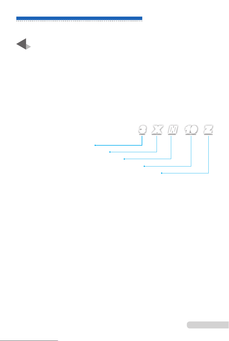
研磨铣刀片的表示
Code key for ground milling inserts
研磨铣刀片型号由型式代号,铣刀片代号(包括切削刃后角代号)和内切圆直径
数字代号组成必要时再缀以左切刀(z)或右切刀(Y)
The code for ground milling inserts consists of the code for the type. code for
milling inserts (including code for the clearance angle of the cutting edge)and
the IC code.When necessary.Z or Y is added to represent left hand or right
hand inserts
C
正三边形代号
Code for equilateral triangle
铣刀片代号
Code for milling inserts
带后角代号
Code for the clearance angle
内切圆直径10mm
IC l0mm
左切片
Left hand inser
t
3 X H 10 Z
精磨刀片表面粗糙度不低于1.25μm.
The surface nish of the ground inserts shall be l.25 microns minimum.
刀片毛坯内孔(固定孔)尺寸允许偏差±0.13mm。
The tolerance of the inner hole(xation hole)of the blanks is+/-0.13mm
法向后角允许偏差≤1°
The tolerance of the clearance angle is
≤
1°
刀片毛坯底面允许内凹0 .1mm。
A concave of O.1mm is allowed on the bosom of the insert blank.
毛坯工作刃部毛刺不得大于0.2mm,其它部位不得大于0.3mm.
The chip on the cutting edge should be no more than 0.2mm and 0.3mm is
allowed in other places.
毛坯工作刃部不允许粘料,其他部位允许轻度粘料。
No lump material should stick to the cutting edge of the blanks and a light
adhesion is allowed in other places.
B
04
硬质合金机夹刀片
Cemented Carbide Indexable Inserts
B
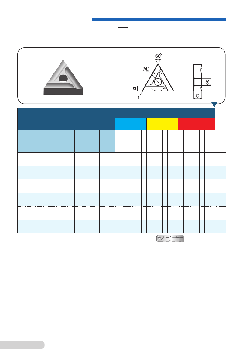
车削
Turning
型号
Type
基本尺寸
Dimension(mm)
基本牌号 Basic grades
防
伪
标
识
P M K
右
Right
左
left
Ø
D
Tol.
C
±0.13
ød
±0.13
r
a≈
31005A 31005AZ
10±0.08 4.5 4.2 0.5 2.4
○ ○ ● ● ● ○ ● ● ● ○ ● ● ● ● ○
*
31305A 31305AZ 13±0.13 5.5 5.2 0.5 3.4
○ ○ ● ● ● ○ ● ● ● ○ ● ● ● ● ○
*
31305A4 31305A4Z 13±0.13 5.5 5.2 0.5 4.4
○ ● ● ● ○ ● ● ● ○ ● ● ● ● ○
*
31605A 31605AZ 16±0.18 7.0 6.2 0.5 4.4
○ ● ● ● ○ ○ ● ● ○ ● ● ● ● ○
*
31605A5 31605A5Z 16±0.18 7.0 6.2 0.5 5.4
○ ● ● ● ○ ○ ● ● ○ ● ● ● ● ○
*
31905A 31905AZ
19±0.18 8.5 7.2 0.5 5.4
○ ● ● ● ○ ○ ● ● ○ ● ○ ● ● ○
*
YT05
YT15
YC201
YT14
YT5
YC45
YS8
YS2T
YW1
YW3
YM201
YW2
YG3X
YG3
YM201
YG6X
YG6
YD201
YG8
●
属半封闭断屑槽,前角为20°左右,适用于切削用量变化不大的外圆车削。
●
主要用于钢材的半精加工。
●
切削用量推荐 :f
n
=(0.15~0.6)mm/rev a
p
=(1.0~6.0)mm
●
It is semi closed chipbreakers with an rake angle of approx 20°.It is suitable for turning peripheries
where there are no big variations of cutting parameters.
●
It is mainly used for the semi-finishing of steel.
●
Recommended cutting parameters: f
n
=(0.15~06)mm/rev a
p
=(l.0~6.0)mm
Anti-forgery
*
表示该型号产品压有防伪标识 Anti-forgery in the product mould
B
05